
 中文简体
中文简体 English
 русский
Content
- 1 How Spring Loaded Safety Relief Valves Work
- 2 Spring Loaded vs. Pilot Operated vs. Bellows Valves: A Side-by-Side Comparison
- 3 ASME Section I vs. Section VIII: What’s Different for Spring Loaded Valves
- 4 Material Selection Guide: Carbon Steel, Stainless Steel, and PTFE-Lined Valves
- 5 Installation Best Practices: 5 Critical Mistakes to Avoid
- 6 Troubleshooting Common Failures: Leakage, Chatter, and Seat Wear
- 7 Cost Analysis: Total Cost of Ownership for Imported vs. Domestic Valves
A single undersized spring loaded safety relief valve on a steam drum can force an entire power plant offline. That one device, no larger than a briefcase, shoulders the entire overpressure protection burden. Yet most procurement engineers spend less than 10% of their selection time on the relief valve itself—until a catastrophic failure turns it into a full-time crisis. This guide collapses the decision process into five actionable steps: understanding the operating principle, comparing valve types, decoding ASME and API requirements, matching materials to process fluids, and quantifying total cost of ownership.
How Spring Loaded Safety Relief Valves Work
A spring loaded safety relief valve balances a compressed helical spring against the process pressure acting on a disc. The spring preload sets the opening point. When system pressure exceeds that set pressure, the disc lifts and the valve discharges. The relationship is straightforward: F_spring = P_set × A_disc, where A_disc is the effective area of the disc exposed to the inlet pressure. Once the disc lifts, a larger area—often the full disc face—becomes exposed to the flowing fluid, creating a rapid pop-open characteristic common in safety valves for compressible fluids.
The sequence follows a predictable cycle. As pressure climbs past the set point, the disc starts to crack open. In a gas or vapor service, the sudden increase in exposed area pushes the disc fully open within 3–5% above set point. Liquid service valves, however, use a more gradual opening because the fluid is incompressible and sudden full lift can cause destructive water hammer. After the overpressure event subsides, the valve reseats when the system pressure drops below the blowdown level—typically 2–7% below set pressure for compressible fluids and 10–20% for liquids.
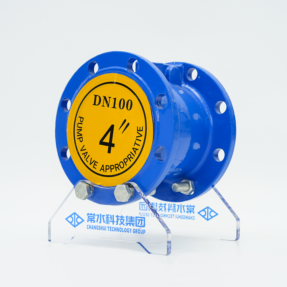
Two internal geometries govern performance: conventional and balanced bellows. Conventional valves have the entire disc area exposed to the inlet pressure, making them sensitive to backpressure on the discharge side. Balanced bellows designs use a bellows element to isolate the disc from backpressure, essential when the relief outlet connects to a common flare header or a closed blowdown system. Many spring loaded safety relief valves can be converted from conventional to bellows simply by swapping the internal spring module—a cost-efficient upgrade path in brownfield applications.
Spring Loaded vs. Pilot Operated vs. Bellows Valves: A Side-by-Side Comparison
Three relief valve technologies dominate the market, and each excels under different constraints. Spring loaded designs remain the most common because they provide full opening with no external power source and tolerate elevated backpressure when equipped with a bellows. Pilot operated valves, by contrast, use a small pilot valve to sense upstream pressure and direct system media to open the main valve. This delivers a tighter blowdown—often 2%—and maintains nearly full capacity right up to the set point. The trade-off is complexity: a pilot valve adds a small filter, a sensing line, and more potential leak paths.
Bellows valves, whether used in spring or pilot configurations, add a metallic or elastomeric bellows to shield the spring and guide from process fluid. This is non-negotiable in corrosive services where product contamination of the spring would cause immediate set point drift. Below, a direct comparison sorts the key parameters for a typical 2-inch orifice, 150-pound class steam application:
| Parameter | Spring Loaded (Conventional) | Spring Loaded (Bellows) | Pilot Operated |
|---|---|---|---|
| Blowdown range | 5–7% | 5–7% | 2–3% |
| Backpressure limit (% of set) | 10% | 50% | 70% |
| Discharge coefficient Kd | 0.975 | 0.975 | 0.975 |
| Leakage at 90% set pressure | Zero (metal seat) | Zero (metal seat) | Zero (soft or metal seat) |
| Minimum inlet pressure loss | 3% | 3% | 1% |
| Relative installed cost | 1.0× (baseline) | 1.4× | 2.2× |
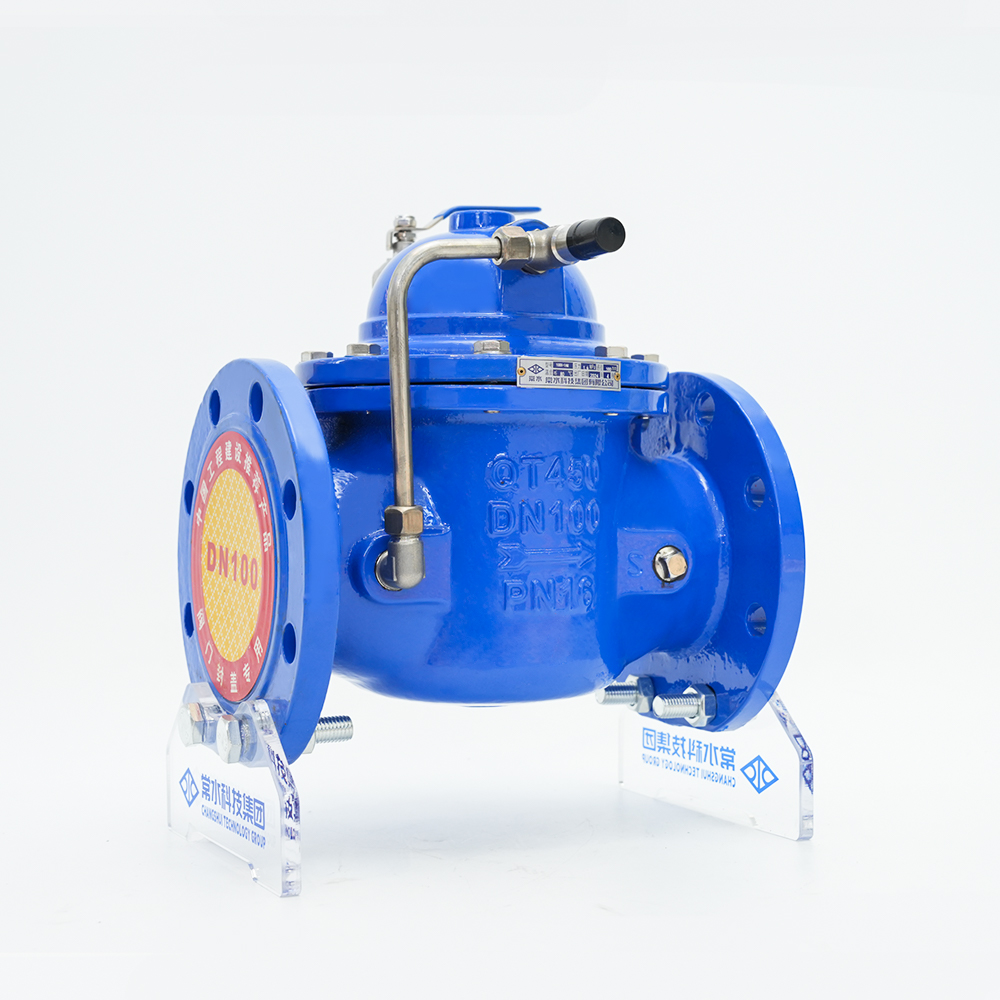
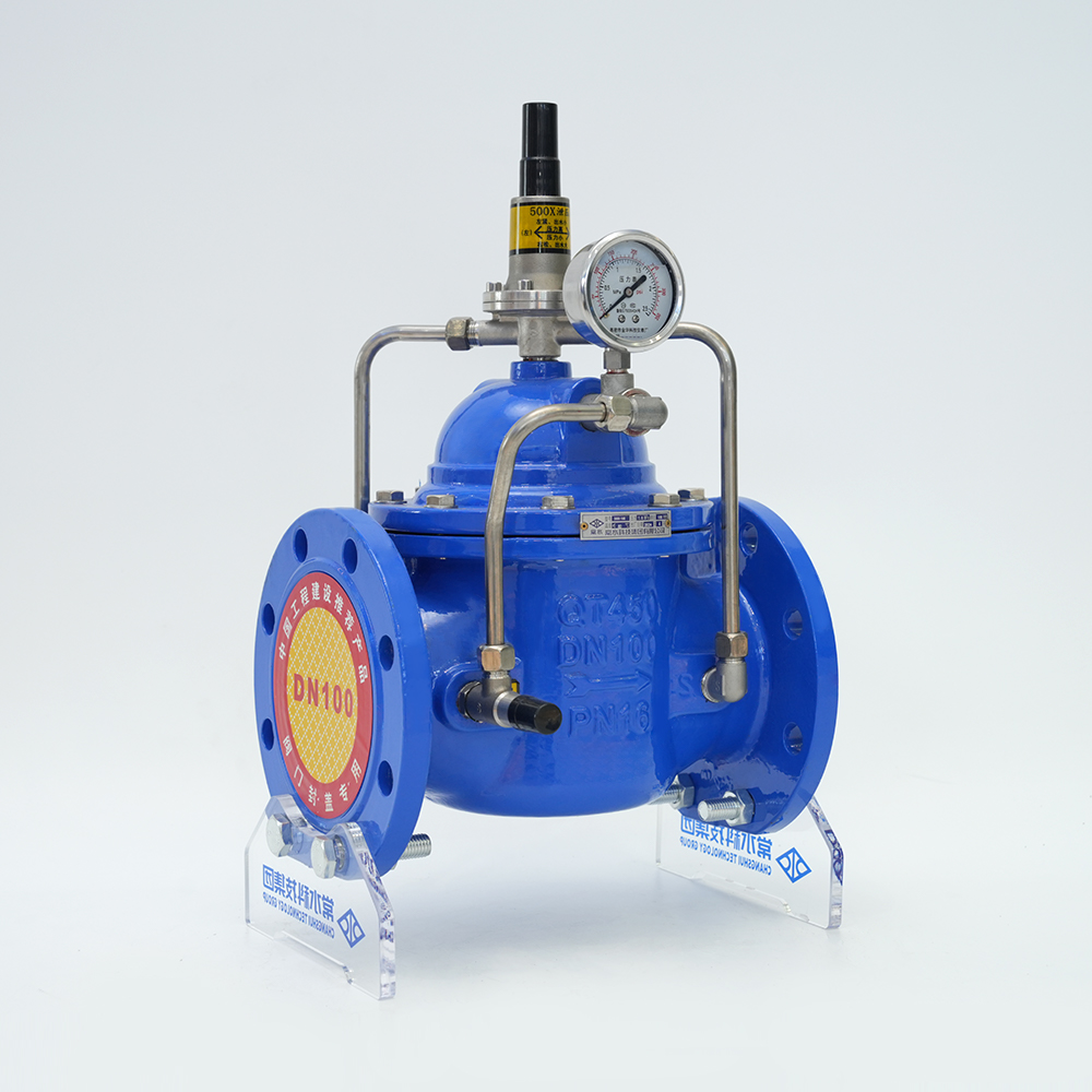
For steam and clean gas services with stable backpressure, the spring loaded bellows valve offers the best balance of performance and cost. In liquid services or applications requiring a very low reseat pressure, a pilot operated valve is worth the premium. The conventional spring loaded safety relief valve is the go-to for standalone vent stacks and non-corrosive fluids where backpressure stays below 10% of set pressure. Ductile iron spring loaded relief valves meet this profile for water, non-pulsating liquids, and low-pressure steam, delivering robust protection without the added cost of bellows.
ASME Section I vs. Section VIII: What’s Different for Spring Loaded Valves
ASME certification is not a single passport—it splits into two parallel paths with markedly different requirements. Section I covers boilers; Section VIII governs pressure vessels. The distinction matters most at the set pressure tolerance, blowdown acceptance window, and the type of capacity certification the valve must carry. Choosing a Section VIII valve for a boiler header can result in a non-compliant installation even if the model number appears correct.
| Requirement | ASME Section I (Boilers) | ASME Section VIII (Pressure Vessels) |
|---|---|---|
| Set pressure tolerance | ±1% (or ±15 psi, whichever is greater) | ±3% (or ±2 psi for ≤70 psig) |
| Blowdown acceptance band | 2–4 psi (or 2–4%, depending on regulation) | Not specifically mandated; typically 5–10% |
| Capacity certification | Full-lift flow test per UG-131, must be witnessed by ASME-designated observer | Office of Licensed Engineer (OLE) capacity test is accepted; lower administrative overhead |
| Valve population per vessel | Minimum one valve; multiple valves allowed only if combined capacity meets demand | Multiple valves allowed; staggered set pressures permitted up to 105% of MAWP |
| Material restrictions | Carbon steel bodies with bronze trim discouraged above 406°F; cast iron prohibited for superheater outlets | Broader material options; cast iron permitted up to class 125 and 250 ratings |
A spring loaded safety relief valve stamped with Section I must be installed within the two feet of the boiler nozzle without any intervening isolation valve. Section VIII valves may be placed farther downstream, but a common mistake is to install a Section I valve on a downstream separator vessel. The mismatch triggers a violation during jurisdictional inspection, often requiring an emergency valve replacement. For systems operating right at the borderline—such as a large hot water storage tank in a district heating plant—many engineers default to Section I certification for the added safety margin, even if not strictly required.
Material Selection Guide: Carbon Steel, Stainless Steel, and PTFE-Lined Valves
The body and trim material of a spring loaded safety relief valve determines whether it survives the first batch of corrosive product or fails silently within weeks. Three material groups cover 90% of industrial applications: carbon steel (ASTM A216 WCB), stainless steel (ASTM A351 CF8M), and PTFE-lined ductile iron. The decision hinges on temperature, corrosion rate, and whether the process fluid can tolerate a minor iron contamination.
| Service Medium | Carbon Steel (WCB) | Stainless Steel CF8M (316L equivalent) | PTFE-Lined Ductile Iron |
|---|---|---|---|
| 200°C saturated steam | Yes; 20-year life if condensate pH >7 | Yes; no added benefit unless chlorides present | No; maximum service temperature 150°C |
| 30% hydrochloric acid at 25°C | No; corrosion rate >5 mm/year | Not recommended; pitting in stagnant acid | Yes; zero metal contact |
| Dry nitrogen, 300 psig, ambient | Yes; no corrosion concerns | Yes; over-spec, higher cost | Not needed |
| Sodium hydroxide 20% at 80°C | Yes; stress corrosion cracking possible above 50°C if residual stress present | Yes; excellent resistance | Yes; but verify NaOH permeation rate at temperature |
| Deionized water at 90°C | Yes; iron pickup may be unacceptable for electronics | Yes; preferred for ultra-pure systems | Yes; suitable but limited to low-pressure applications |
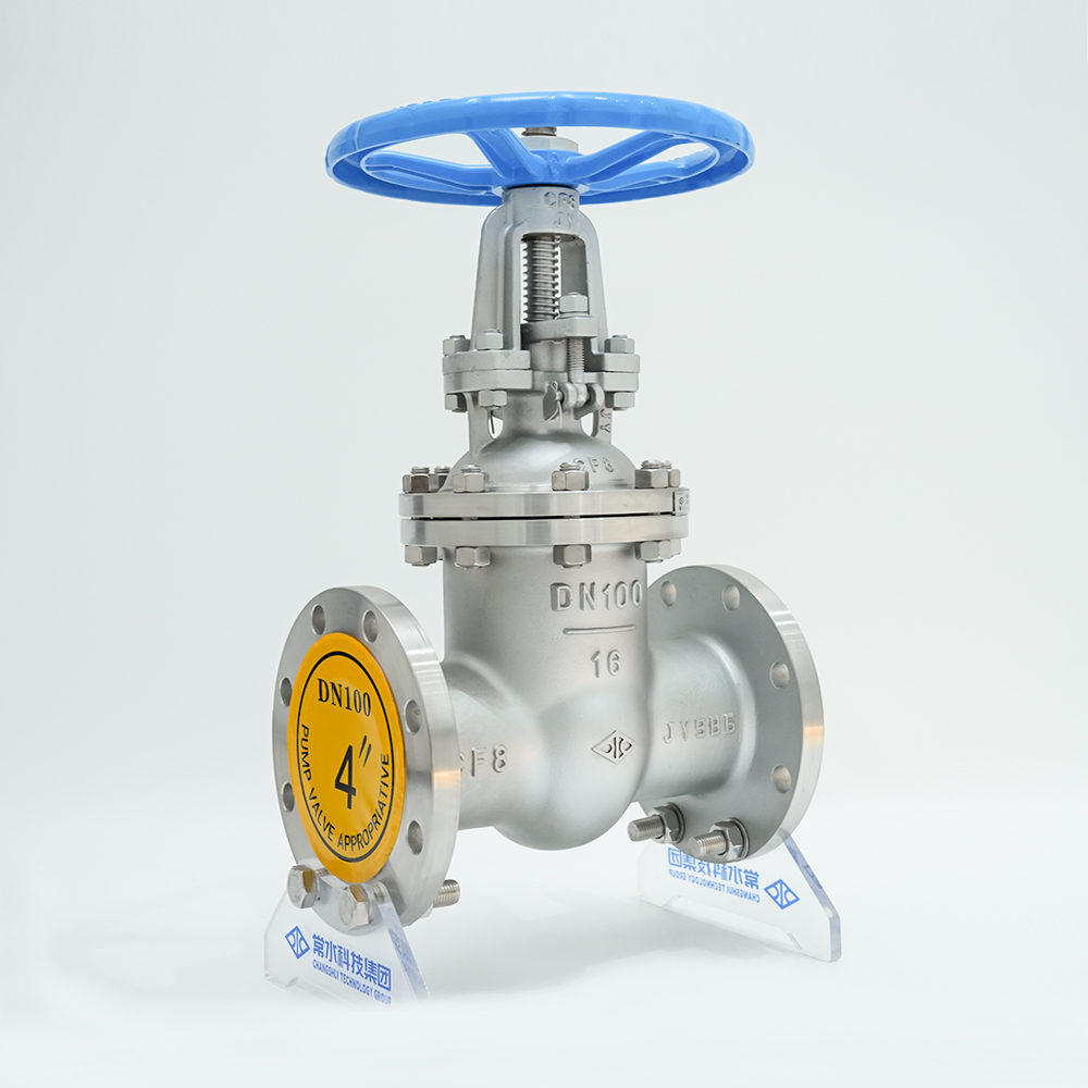
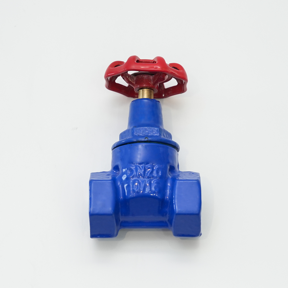
Carbon steel remains the default choice for steam, air, and neutral liquids at moderate temperatures. Its cost per installed pound is the lowest, and spare parts are universally available. Stainless steel is mandated whenever the process cannot tolerate iron contamination or when chlorides above 50 ppm are present. PTFE-lined valves, such as ductile iron gate valves with full fluoropolymer lining, eliminate metal exposure entirely but require derating for temperature and pressure—typically 10% of the cold working pressure at 150°C. For aggressive acid or mixed-chemical waste streams, the lined option often pays back within six months by avoiding quarterly valve replacements.
Installation Best Practices: 5 Critical Mistakes to Avoid
Even the best-calibrated spring loaded safety relief valve performs poorly when installed incorrectly. Years of plant audits reveal five recurring errors that compromise relief capacity or accelerate wear.
- Non-vertical orientation. A spring loaded safety relief valve must be mounted within 2 degrees of true vertical. Anything beyond 3 degrees causes the disc to bind against the guide, delaying opening and increasing blowdown. Install a mounting bracket with an integrated spirit level or use a laser alignment tool before torquing the flange bolts.
- Discharge piping backpressure exceeding 10% of set pressure. In a conventional valve, backpressure adds directly to the closing force on the disc, raising the actual set point. If the discharge header ties into a flare system that runs at 15 psig during a blowdown, a valve set at 100 psig effectively opens at 115 psig. The fix is to switch to a bellows-equipped valve or oversize the discharge line to keep backpressure below 10% of set.
- Inlet pressure loss above 3%. The Code (ASME VIII) requires that the non-recoverable pressure loss between the vessel and the valve inlet does not exceed 3% of the set pressure. Long, undersized inlet lines or a full-bore strainer without a blow-down bypass can easily exceed 5% loss, causing the valve to flutter—a rapid open-close cycle that hammers the seat and disc. Increase the inlet pipe diameter by one size or shorten the spool piece to stay within the limit.
- Block valve inadvertently left closed. Any stop valve installed between the protected vessel and the relief valve inlet must be locked or car-sealed open and inspected monthly. A single missed lock-out has led to multiple boiler explosions documented in ASME case histories. Use a proximity sensor wired to the control room DCS if possible.
- Mixing spring materials with incompatible environments. Standard spring steel (chrome-silicon) corrodes rapidly in H2S service above 50 ppm, leading to spring relaxation and drifting set points. In sour service, specify Inconel X-750 or Hastelloy C-276 springs. The $600 adder protects a $6,000 valve and, more importantly, the million-dollar vessel behind it.
Troubleshooting Common Failures: Leakage, Chatter, and Seat Wear
When a spring loaded safety relief valve begins leaking at 85% of set pressure or chatters during a test, the root cause is almost always mechanical—not a calibration error. Systematic troubleshooting follows a logical chain: seat leakage, disc instability (chatter), then material degradation.
| Symptom | Most Likely Cause | Corrective Action |
|---|---|---|
| Valve leaks below set pressure at ambient temperature | Foreign particle trapped between seat and disc; or seat misalignment after thermal cycling | Perform hot torque of the nozzle seat lap; flush inlet with nitrogen. If leakage persists, inspect seat flatness under blue light and re-lap or replace the disc. |
| Valve chatters or flutters during liquid service | Inlet pressure loss exceeds 3% (see installation mistake #3) or the disc/lift mechanism resonating with system pulsation | Increase inlet line diameter; add a pulsation damper or a softer spring with a wider blowdown band. For persistent liquid chatter, consider converting to a soft-seated disc to increase damping. |
| Seat eroded with wire-drawn streaks | Cavitation during partial opening in liquid service; or flashing condensate in steam lines | Install a downstream backpressure regulator to maintain minimum backpressure, preventing cavitation. Upgrade to a Stellite 6 hard-faced seat and disc. |
| Spring set point has drifted downward by >5% | Spring fatigue or stress relaxation, often from exposure to temperatures above the spring's rating (typically 450°F for chrome-silicon) | Replace spring with high-temperature alloy (Inconel 718). Verify that bonnet ventilation prevents heat soak from adjacent piping. Reset and witness-tag the set pressure. |
| Bellows rupture (bellows valve) | Fatigue cracking from excessive full-stroke cycles; or chemical attack from condensate trapped inside bellows | Replace bellows element. Add a drain hole in the bonnet to vent trapped liquids. Consider increasing service frequency inspection to every six months. |
After any significant repair—lapping the seat, replacing the spring, or swapping the disc—the valve must be reset and tested on a certified test stand. A simple bench test with shop air is not sufficient for compliance. An ASME-certified repair facility will perform a full set-pressure and seat-tightness test using nitrogen or steam according to the original National Board Inspection Code (NB-23) procedures. Many plants schedule a spare spring loaded safety relief valve on a rotating basis, allowing in-kind replacement while the removed valve goes out for overhaul, which minimizes process downtime.
Cost Analysis: Total Cost of Ownership for Imported vs. Domestic Valves
The purchase price of a 2-inch spring loaded safety relief valve ranges from $400 to $3,000 depending on materials and certifications. Over a 10-year operating life, the initial purchase accounts for only 12–15% of total cost. Service swaps, spare parts, and a single unplanned outage dwarf procurement savings. A true TCO comparison must compare initial cost, spare part availability, technical support response time, and the expected intervals between overhauls.
| Cost Component | Imported Valve (Typical Far-East Source) | Domestic Valve (e.g., 500X Series) |
|---|---|---|
| Initial valve purchase | $1,200 | $1,800 |
| Spare parts (one set of soft goods, spring, disc) | $900 (60-day lead time) | $450 (stocked in-country) |
| Annual inspection and recertification (2 cycles over 5 years) | $600 (sent to third-party lab; 4-week turnaround) | $400 (certified local service center; 5-day turnaround) |
| Unplanned outage cost — assuming one failure in 5 years (labor + lost production, 36 hours) | $14,000 (delayed spare parts extends outage) | $8,000 (express part shipment reduces outage by 18 hours) |
| Technical support (engineering calls, field advisory) | $0 (limited email support, language barrier) | $0 (direct engineer response within 4 hours) |
| Total 5-year TCO | $16,700 | $10,650 |
The domestic option shows a 36% lower total cost despite a 50% higher initial price. The swing factor is downtime: a single 36-hour outage caused by a missing spare part erases 15 years of purchase-price savings. In a chemical plant producing $5,000 per hour of product, the math becomes even more lopsided. Many plant reliability managers now mandate a local inventory of one complete spare valve per critical service, stored at the site or at a regional warehouse with a 24-hour guarantee. This strategy pairs effectively with stainless steel flanged gate valves for isolation and a dedicated relief valve skid, ensuring that a single unit failure never isolates the protection layer.