
 中文简体
中文简体 English
 русский
Content
- 1 What Is an Actuator on a Butterfly Valve and How Does It Work?
- 2 Electric vs Pneumatic vs Hydraulic Actuators: A Side-by-Side Comparison
- 3 How to Calculate Actuator Torque for Butterfly Valves (With Examples)
- 4 Resilient Seated vs Metal Seated Butterfly Valves: Which Seal Type Do You Need?
- 5 Understanding Triple Offset Design and Its Impact on Actuator Selection
- 6 Actuator Installation Best Practices: Mounting, Wiring, and Air Supply
- 7 Common Actuated Butterfly Valve Failures and Troubleshooting Steps
- 8 Industry Standards and Certifications You Should Know (API 609, ISO 5211, ATEX)
What Is an Actuator on a Butterfly Valve and How Does It Work?
A poorly sized actuator can turn a high-performance butterfly valve into a maintenance nightmare. Yet with the right match, the same valve delivers years of trouble-free isolation or modulating control.
An actuator is the mechanical device that converts external energy into the rotary motion needed to open or close the butterfly valve disc. The disc is mounted on a shaft that passes through the valve body. When the actuator rotates the shaft 90 degrees, the disc swings from a fully closed position (perpendicular to flow) to fully open (parallel to flow).
In an electric actuator, an electric motor drives a gear train that turns the valve stem. Pneumatic actuators use compressed air to move a piston or a rack and pinion mechanism. Hydraulic versions rely on pressurized oil for high-force applications. Regardless of the power source, the principle is the same: controlled rotation of the disc governs flow.
The actuator must overcome breakaway torque – the force needed to unseat the disc from its sealing surface – and then supply enough running torque to hold the disc at the desired angle. Selecting an actuator without verifying these torque values is the single most common cause of early valve failure.
Electric vs Pneumatic vs Hydraulic Actuators: A Side-by-Side Comparison
The right power source depends less on the valve itself and more on site conditions, control requirements, and long-term operating costs. A facility with an existing air network will lean pneumatic; a remote pumping station with no air supply and a need for precise modulation will favor electric.
| Parameter | Electric | Pneumatic | Hydraulic |
|---|---|---|---|
| Control Precision | High (0.1–0.5% positioning accuracy) | Moderate (1–2%) | Moderate (1–3%) |
| Response Time | Slower (2–15 seconds per 90°) | Very fast (under 1 second) | Fast (1–3 seconds) |
| Power Source | 24 VDC / 110 VAC / 220 VAC | Compressed air (4–8 bar) | Hydraulic power unit (oil, 70–210 bar) |
| Initial Cost Range | $500–$2,000 | $300–$1,500 | $800–$3,000 |
| Operating Cost | Low (electricity only) | Higher (compressor, dryer, air leaks) | Highest (oil changes, pump upkeep) |
| Typical Size Range | 2"–24" | 2"–48" | 6"–60" |
| Best Applications | Precise modulating control, remote sites with power but no air | Hazardous areas, high-cycle on/off, fire-safe systems | Very large valves, high-pressure drops, subsea or heavy-duty |
Electric actuators shine when you need 0.1% positioning accuracy for flow control loops. They accept 4–20 mA or Modbus signals and can stop the disc at any intermediate angle. Pneumatic spring-return actuators dominate safety-critical services because they fail closed (or open) on loss of air. Hydraulics are rarely the first choice unless torque demands exceed what electric or pneumatic can deliver – think 48-inch butterfly valves operating at 25 bar differential.
From a total cost perspective, the initial price advantage of pneumatic actuators often erodes over five years. A 10-inch pneumatic setup may cost $800 upfront, but maintaining a dedicated air compressor and dryer adds 15–25% annually in energy and service. An equivalent electric actuator costing $1,200 pays back within three years through lower energy consumption and zero air loss.
How to Calculate Actuator Torque for Butterfly Valves (With Examples)
Actuator sizing always starts with breakaway torque – the peak torque needed to unstick the disc from the seat. Running torque, the force to rotate the disc mid-travel, is typically 30–40% lower. The actuator must deliver at least the breakaway torque with an added safety margin.
The safety factor accounts for service fluid, pressure spikes, and seat aging. Clean water applications can use a factor of 1.3. For viscous or slurry media, the recommended factor rises to 1.5–2.0. A valve handling raw sewage or abrasive mining slurry demands a safety factor of 2.0 to avoid stalling mid-stroke.
| Valve Size (DN) | Media Type | Breakaway Torque (Nm) | Safety Factor | Required Actuator Torque (Nm) |
|---|---|---|---|---|
| DN100 (4") | Water | 35 | 1.3 | 46 |
| DN150 (6") | Water | 85 | 1.3 | 110 |
| DN150 (6") | Slurry | 85 | 1.8 | 153 |
| DN200 (8") | Oil | 150 | 1.5 | 225 |
As a practical rule, verify the actuator’s torque rating at the valve’s closing angle. Many electric actuator torque curves drop at the extreme end of travel; if the curve dips below the required breakaway torque, the valve will fail to fully seat and will leak. Always request the manufacturer’s torque curve, not just the catalog maximum.
Resilient Seated vs Metal Seated Butterfly Valves: Which Seal Type Do You Need?
Seal material determines the valve’s temperature envelope and leak-tightness. Resilient seated (soft-seal) butterfly valves use a polymer liner – typically EPDM, NBR, or PTFE – that the disc presses into to achieve zero leakage. Metal seated designs rely on a metal-to-metal contact, accepting a small, controlled leak rate in exchange for heat resistance.
| Seal Type | Temperature Range | Leakage Class | Suitable Media | Actuator Torque Influence |
|---|---|---|---|---|
| Resilient Seated (Soft) | -20°C to 120°C | Zero leakage (Class VI) | Water, cooling water, mild chemicals | Lower torque; smooth breakaway |
| Metal Seated | -50°C to 400°C | Class IV or lower | Steam, hot oil, chemical solvents | Higher torque due to friction; torque spike near close |
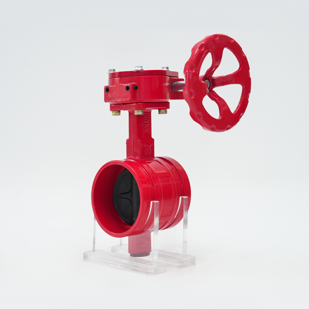
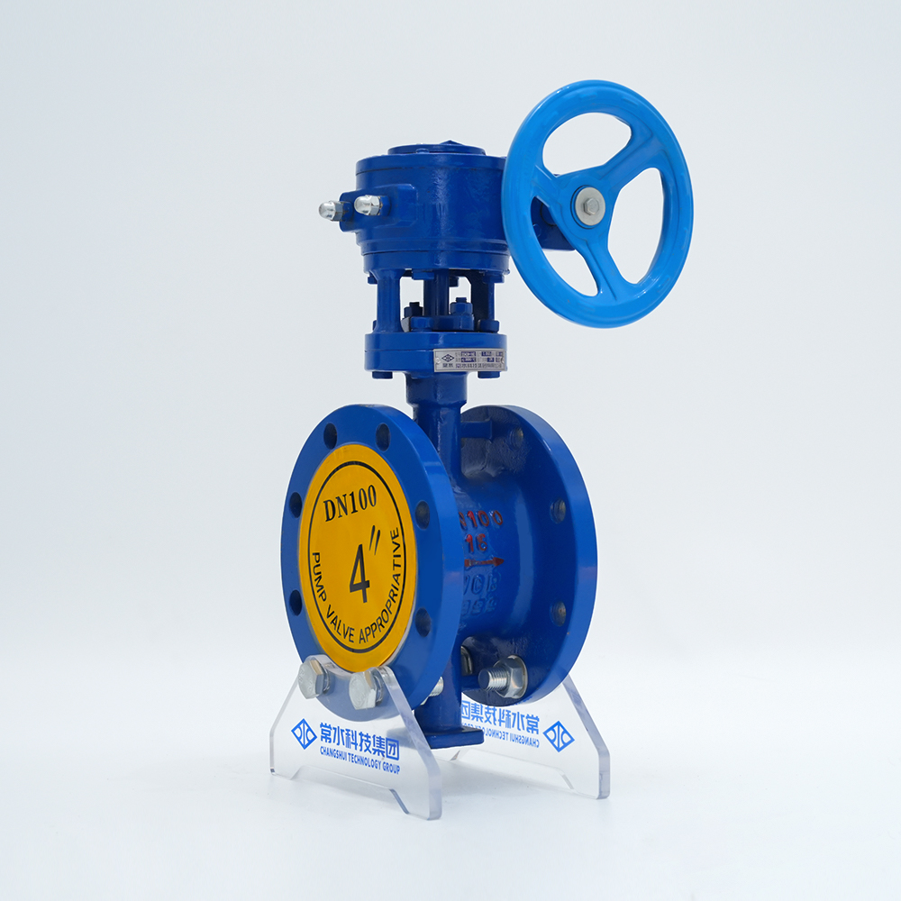
For municipal water networks and HVAC systems, resilient seated designs achieve bubble-tight shutoff with minimal actuator torque. Ductile iron butterfly valves with EPDM liners are the workhorses here. When the media temperature exceeds 120°C, only a metal seated valve survives. High-temperature steam lines and refinery transfer applications often use cast steel butterfly valves with hardened metal seats and a triple offset geometry to achieve near-zero leakage despite the thermal cycling.
Understanding Triple Offset Design and Its Impact on Actuator Selection
A triple offset butterfly valve positions the shaft behind the disc centerline, tilts the sealing cone, and uses a metal seat with elliptical geometry. The result: the disc touches the seat only in the final milliseconds of closing, eliminating the wiping wear common in concentric valves.
That geometry delivers zero leakage metal seals but creates a unique torque curve. The breakaway torque for a triple offset valve is not the highest reading; instead, the torque spikes sharply at the very end of the closing stroke – often 20–30% higher than the mid-cycle torque. An actuator must deliver its full rated torque at precisely that 90-degree position. Electric actuators with built-in torque switches can be set to cut off at that peak, while undersized pneumatic actuators will stall and leave the valve partially open.
Actuator Installation Best Practices: Mounting, Wiring, and Air Supply
Even a perfectly sized actuator will fail early if the installation ignores mechanical alignment and environmental sealing. These seven steps prevent most on-site headaches:
- Match the ISO 5211 flange pattern. Common sizes are F05, F07, and F10. A mismatched flange leads to stripped bolts or eccentric loading.
- Verify stem dimensions. The actuator drive socket must fit the valve stem’s square or keyed end without excess clearance. Slack causes hammering and wear.
- Mount vertically or support weight. Heavy electric actuators on horizontal pipelines need extra bracketry; sagging misaligns the stem over time.
- Electric wiring: confirm voltage and grounding. 24 VDC, 110 VAC, or 220 VAC actuators are not interchangeable. Always bond the actuator body to plant ground.
- Pneumatic air quality. Supply clean, dry air at 4–8 bar. Install a coalescing filter and regulator; moisture damages seals and positioners.
- Set limit switches before powering up. Blindly rotating an actuator beyond its mechanical stop will destroy the gear train or valve seat.
- Avoid pipe strain. Do not use the valve or actuator as a pipe support; install expansion joints if thermal growth is expected.
Common Actuated Butterfly Valve Failures and Troubleshooting Steps
Most field problems trace back to three root causes: improper torque sizing, contaminated supply media, or installation misalignment. The table below covers the most frequent symptoms and their first-level corrective actions.
| Symptom | Possible Cause | Solution |
|---|---|---|
| Valve stem binding or stiff operation | Lack of bearing lubrication; bent stem from side load | Lubricate bearings per manual; check coupling alignment and support actuator weight |
| External seat leakage | Worn liner or insufficient actuator torque at final close | Replace seat; verify actuator torque setting meets breakaway requirement at 90° |
| Actuator does not respond to command | Loss of power (electric) or air supply; blown fuse; signal wiring fault | Check power source, fuses, and control signal; measure 4–20 mA loop integrity |
| Valve fails to fully open or close | Actuator undersized or pressure spike exceeds design condition | Recalculate torque with actual differential pressure; upgrade actuator or increase safety factor |
| Water or moisture inside electric actuator | Damaged O-ring or condensation from temperature cycling | Replace housing seals; install a breather drain and desiccant cartridge |
| Pneumatic actuator hissing or leaking air continuously | Worn piston seal or loose air fittings | Replace piston seal kit; tighten fittings and check with soapy water |
| Erratic positioning or oscillation | Contaminated positioner or loose feedback linkage | Clean positioner nozzle/flapper; recalibrate zero and span; tighten linkage |
When a failure repeats, look beyond the actuator itself. A valve stem that bends repeatedly indicates a misapplied valve for the pressure class or an unsupported heavy actuator hanging off the valve neck.
Industry Standards and Certifications You Should Know (API 609, ISO 5211, ATEX)
Compliance with international standards is not just paperwork – it directly affects actuator interchangeability, explosion safety, and valve longevity.
- API 609 (Butterfly Valves: Lug- and Wafer-Type): Defines pressure-temperature ratings, minimum wall thickness, and seat leakage criteria. A butterfly valve meeting API 609 ensures the shell and seat can handle rated pressures without distortion that would overload the actuator.
- ISO 5211 (Part-turn actuator attachment): Specifies flange dimensions, drive squares, and torque patterns. A valve with an ISO 5211 F07 pad accepts any F07-pattern actuator without custom brackets, simplifying replacement.
- ATEX / IECEx (Explosive atmospheres): Electric and pneumatic actuators installed in Zone 1 or 2 areas must carry ATEX II 2G Ex d IIC T4 or equivalent certification. The certification covers not just the motor but the complete actuator assembly including limit switches.
- NEMA / IP enclosures: Electric actuators in washdown or outdoor locations need NEMA 4X or IP66 protection to prevent water ingress and early failure.
Demanding proof of these certifications during procurement eliminates the risk of a non-compliant actuator causing a plant shutdown.