
 中文简体
中文简体 English
 русский
Content
What Does a Check Valve Symbol Mean?
A check valve symbol on a P&ID is not just a sketch. It defines the one allowed flow path and the direction that fluid must travel. Every line, arrow, and geometric shape inside that symbol has a purpose: to prevent backflow from damaging pumps, contaminating clean lines, or creating water hammer in the system.
At its core, a check valve symbol communicates three things. First, the direction of allowed flow — typically shown by an arrow, a triangle, or a vertical stem. Second, the internal closing mechanism — a ball, disc, or swing flap that opens under forward pressure and seals when flow stops or reverses. Third, whether the valve relies on gravity alone or includes a spring to assist closing. Those three elements appear consistently across P&ID, hydraulic, and pneumatic drawing standards, even when the shape changes slightly.
If you can read those three elements, you already know whether the real valve must be installed horizontally, vertically, or at an angle. You also know whether the valve needs pressure behind it to close or whether a spring will do the job even in a dead-end line.
How to Read Check Valve Symbol Flow Direction
Flow direction on a check valve symbol follows a simple rule: the arrow, triangle apex, or flow path line points toward the downstream side of the valve. The fluid enters from the opposite side and lifts the disc or ball off the seat. If you reverse the installation, the flow pushes the closure element onto the seat and the valve stays shut — permanently.
In a P&ID symbol, you normally see a straight line interrupted by a slanted or perpendicular mark inside a circle or a bow-tie shape. The flow arrow is drawn outside the symbol or integrated into the line. A good habit is to trace the main process line from pump discharge forward; the arrow on the check valve must point in that same direction.
Hydraulic symbols (ISO 1219) use a different geometry — a spring symbol and an angled seat — but the logic is identical. The triangle inside the hydraulic symbol points in the direction of allowed flow. If the triangle points to the right, fluid can only travel left‑to‑right. In pneumatic diagrams, often a small “v” or arrowhead is embedded in the valve enclosure, and the flow path is blocked in the reverse direction by a perpendicular line.
When the symbol includes a spring, flow direction interpretation gets one extra layer. The spring is drawn on the downstream side of the closure element. That means forward pressure must overcome both the spring force and any backpressure to open the valve. In systems with low differential pressure, selecting a spring‑assisted check valve from a drawing symbol without checking the required cracking pressure can lead to a permanently closed valve.
P&ID, Hydraulic, and Pneumatic Check Valve Symbols
Different engineering disciplines use their own standard symbol sets, but all of them convey the same unidirectional flow concept. The table below compares the three most common standards you will find on plant drawings, hydraulic schematics, and compressed air layouts.
| Drawing Standard | Typical Symbol Shape | Flow Direction Clue | Common Applications |
|---|---|---|---|
| P&ID (ISO 10628) | Circle or bow‑tie with a short perpendicular line or disc inside | Arrow along the pipe line; the disc line blocks the reverse path | Water, steam, chemical process lines |
| Hydraulic (ISO 1219‑1) | Square with a ball or poppet, spring, and angled seat | Triangle pointing toward allowed flow; arrow may also appear | Hydraulic power units, oil return lines |
| Pneumatic (ISO 1219‑1) | Similar to hydraulic but often no spring; may show a simple check mark | Arrow or flow path line; reverse blocking is a perpendicular bar | Compressed air lines, vacuum systems |
Despite the visual differences, the one constant is the non‑return logic. If you can find the blocking element (the disc, ball, or flap) inside the symbol, you can quickly spot which side is inlet and which is outlet. On P&IDs, the disc is drawn resting against a seat; flow must come from the side that pushes the disc open. On hydraulic schematics, the spring and ball poppet clearly indicate that only forward pressure above the spring preload will allow oil to pass.
Common Check Valve Symbol Variants and What They Suggest
A generic check valve symbol only tells you that backflow is blocked. But the variant details — whether the disc is shown as a flap, a ball, or a piston — give you a strong clue about the actual valve design and its installation limits. The table below maps common symbol variants to real valve types, typical pressure classes, and recommended applications.
| Symbol Variant Feature | Suggested Valve Type | Typical Model | Pressure Rating | Application Notes |
|---|---|---|---|---|
| Swing disc shown inside circle | Swing check valve | H44X‑16Q | PN10/16 | Horizontal lines only; rubber disc check valve suitable for water and non‑aggressive fluids |
| Poppet or globe‑like seat with spring | Lift / silent check valve | HC41X‑16Q | PN16/25 | Vertical or horizontal; spring reduces water hammer |
| Butterfly or wafer body with spring | Dual‑plate or wafer check valve | H77X‑16Q | PN16 | Compact face‑to‑face; install between flanges |
| Ball inside cage with spring | Ball check valve | HQ41X‑16Q | PN10/16 | Low‑pressure drains, fuel lines |
| No spring, angled seat | Lift check valve (gravity‑closing) | H41X‑16P | PN16/25 | Must be installed vertically or at angle; often used with stainless steel silencer check valves |
This mapping is not just academic. A drawing that shows a swing disc symbol on a vertical riser should immediately raise a flag: swing checks can stick open if installed vertically unless they are spring‑loaded. Similarly, if the symbol lacks a spring but the process has frequent flow reversals, you will need a silent check or a slow‑closing model to prevent water hammer. Knowing the symbol variant helps you catch those mismatches before fabrication.
5 Common Mistakes When Reading Check Valve Symbols
Even experienced technicians misinterpret check valve symbols. Small errors on the drawing board turn into expensive rework on the pipe rack. Here are the five most frequent mistakes and how to correct them.
- Assuming the arrow always shows flow direction. In some P&ID legends, the arrow is part of the general line direction, not the valve symbol itself. Always verify against the process flow diagram (PFD) header or the pump discharge nozzle. If the arrow inside the valve symbol conflicts with the main line arrow, treat the valve as closed and walk back through the design intent.
- Ignoring the spring symbol. A spring inside the check valve symbol means the valve needs a minimum cracking pressure to open. In gravity flow applications, that required pressure may never be reached. Check the vendor’s cracking pressure data and compare it with the system operating pressure at the valve inlet. If the static head is less than the cracking pressure, choose a non‑spring check valve or a different location.
- Reading a hydraulic check symbol as bidirectional. On ISO 1219 hydraulic drawings, the check valve is represented as a ball and seat with a spring. Some draftsmen draw a two‑way flow path around the check valve for bypass lines. The check symbol itself is still strictly one‑direction; any flow through the bypass is controlled by a separate directional valve. Never read the bypass as an indication that the check valve allows reverse flow.
- Using a swing check symbol for vertical installations. A swing check without a spring relies on gravity and reverse flow to close. On a vertical up‑flow line, the disc may never fully seat. If the drawing shows a swing check symbol on a vertical line, confirm that the specified model includes a spring or switch to a lift‑check or silent check design.
- Confusing P&ID and piping isometric symbols. On isometric drawings, check valve symbols are often simplified to a circle with a “v” and an arrow. The isometric symbol may not show the disc shape or spring. Always cross‑reference the isometric with the P&ID and the pipe class datasheet to confirm the valve type, connection ends, and orientation limits.
From Symbol to Real Valve Selection: RFQ Checklist
A check valve symbol tells you the flow direction and hints at the internal design. But a real purchase order needs more than a triangle and a circle. Use this five‑point checklist to convert a symbol into a valve specification that a supplier can quote without guesswork.
- Valve type dictated by the symbol. Identify whether the drawing implies a swing, lift, wafer, or ball check. State this explicitly in the RFQ — “spring‑loaded silent check” or “swing check with rubber disc,” not just “check valve.”
- Line size and connection. Note the nominal diameter (DN) from the pipe spec. Confirm the end connection: flanged, threaded, or wafer. A mismatch here is the most common return cause.
- Pressure rating and cracking pressure. The P&ID may show PN16 or Class 150, but if the system experiences surge, specify the required shell test pressure. For spring‑loaded valves, define the minimum opening differential pressure.
- Installation orientation. Based on the symbol variant, declare horizontal, vertical up, vertical down, or allowed angle. If the symbol shows no spring, vertical installation may be impossible without a special design.
- Material and media. The symbol itself does not reveal whether the valve must be ductile iron, stainless steel, or cast steel. Pull the material from the line class sheet. For corrosive media or hygienic service, a ductile iron check valve with epoxy coating or a fully stainless model becomes mandatory.
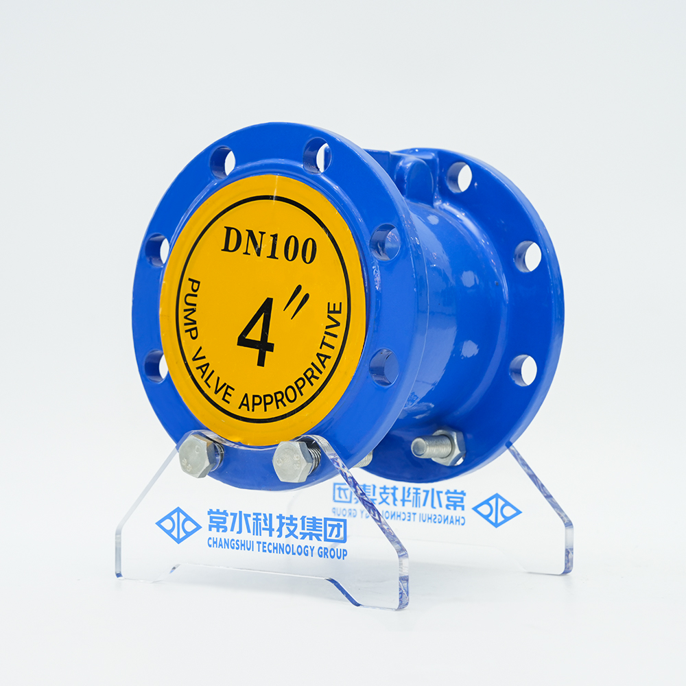
When you attach the relevant drawing crop to the RFQ, mark the flow direction arrow clearly. That single markup eliminates 90% of the back‑and‑forth between engineering and the vendor.