
 中文简体
 English
 русский

Content
- 1 What an ASME Safety Relief Valve Actually Is
- 2 Which Code Section Governs Your Application
- 3 Set Pressure, Overpressure and Accumulation
- 4 Sizing a Relief Valve the Code Way
- 5 Installation Details That Decide Whether the Valve Works
- 6 Matching Body and Trim to the Fluid
- 7 Testing, Documentation and Lifecycle
- 8 A Practical Selection Checklist
Every pressure system has one device whose only job is to fail safely. When a blocked outlet, a jammed regulator or an external fire pushes a vessel past its design pressure, the safety relief valve is the last barrier between a controlled process and mechanical failure. The ASME Boiler and Pressure Vessel Code treats these valves accordingly: it does not simply ask whether the valve works, it asks who certified that it works, at what capacity, and under which conditions.
What follows is a practical walk through the ASME requirements that shape a safety relief valve — which section governs your system, how set pressure and accumulation limits fit together, how capacity is certified, and what to confirm before the valve reaches your line. It is written from the shop floor rather than from the clause list.
What an ASME Safety Relief Valve Actually Is
The terminology is worth sorting out first, because it affects what you order. In ASME and API usage, a safety valve is the pop-action device used on steam and gas, a relief valve opens progressively and is used on liquids, and safety relief valve covers both. On a purchase order the words matter less than the stamp on the nameplate.
Three ASME stamps are relevant: V for Section I power boilers, HV for Section IV heating boilers, and UV for Section VIII pressure vessels. Behind the stamp sits capacity certification — the valve has been flow-tested and its relieving capacity recorded, usually under National Board observation, so an engineer can size the device from published data instead of guesswork.
A valve with identical dimensions, a similar spring and no certification is not interchangeable in code service. That is the first question worth asking any supplier.
Which Code Section Governs Your Application
Section VIII Division 1 is the usual starting point for process equipment: it applies to pressure vessels with a maximum allowable working pressure of 15 psig and above, and its rules for relief devices run from UG-125 through UG-137. Steam boilers, however, belong to Section I, and small heating boilers to Section IV. Fitting a Section I valve to a Section VIII vessel is a nonconformance even when the valve would in fact protect the vessel.
| Code section | Typical scope | Relief device stamp | Governing paragraphs |
|---|---|---|---|
| Section I | Power boilers, steam above 15 psig | V | PG-67 to PG-73 |
| Section IV | Heating boilers, low-pressure steam and hot water | HV | HG-400 to HG-403 |
| Section VIII Div. 1 | Pressure vessels, MAWP 15 psig and above | UV | UG-125 to UG-137 |
| Non-code water systems | Water supply, HVAC and fire protection lines | Not required | Product standard applies |
The selection follows the vessel or the boiler, not the valve catalogue. Read the manufacturer's data report first, then specify.
Set Pressure, Overpressure and Accumulation
Four numbers run through every relief valve specification. The maximum allowable working pressure (MAWP) is the ceiling the vessel is designed for. Set pressure is the inlet pressure at which the valve begins to open under test conditions. Accumulation is the rise above MAWP while the valve is relieving. Blowdown is the drop between popping and reseating, and it is a performance characteristic to confirm with the manufacturer rather than a fixed code figure.
| Parameter | Commonly applied limit |
|---|---|
| Accumulation, normal process upset | 10% or 3 psi above MAWP, whichever is greater |
| Accumulation, fire or external heat | 21% above MAWP |
| Set pressure, single device | At or below MAWP |
| Set pressure tolerance after testing | Plus or minus 2 psi up to 70 psig; plus or minus 3% above 70 psig |
| Multiple devices | At least one set at or below MAWP |
| Inlet line loss | Keep below about 3% of set pressure |
The relationship that trips people up most often is the one between operating pressure and set pressure. A valve set exactly at the MAWP of a vessel that normally runs at 95% of MAWP will simmer, weep and eventually leak. Practical guidance is to keep normal operating pressure below the set pressure by at least 5 psi or 10%, remembering that the spring must still be tested and set within the tolerance above. Where a process cannot tolerate that margin, a pilot-operated or bellows design is usually a better answer than a tighter set point.
Sizing a Relief Valve the Code Way
Certified capacity is the point of the whole exercise. The relief load itself is calculated rather than read from the valve: blocked outlet, control valve failure, thermal expansion and fire are the usual cases, and the largest of them sets the required capacity. Only then does the valve data sheet come into play.
- Fluid and phase at relieving conditions — steam, gas, liquid or two-phase, which changes the sizing equation entirely.
- Relieving pressure and temperature, including the permitted overpressure, because capacity is certified at specific conditions.
- Orifice designation, such as API 526 letter sizes, matched to the calculated required area rather than to the existing pipe size.
- Built-up back pressure: above roughly 10% of set pressure, a conventional valve's capacity is affected and a balanced bellows design is normally specified.
- Material and trim derating for high temperature, plus corrosion allowance in aggressive media.
For a step-by-step view of how these variables narrow the choice, our spring-loaded safety relief valve selection matrix sets out the decision order in detail.
Installation Details That Decide Whether the Valve Works
A correctly certified valve in a badly piped installation protects nothing. Keep the inlet short and generously sized, since inlet loss eats into the 3% allowance and produces chatter, and mount the valve vertically, on the vessel wherever possible. Discharge piping should be supported independently, drained at its low point, and routed so that nobody stands where the valve will vent.
Block valves belong on either side of a relief valve only under a formal procedure: car-sealed or padlocked open, logged, and covered by management of change. Where isolation is genuinely needed for maintenance, a spare-valve arrangement is usually cleaner than a hand valve that someone will eventually close.
Matching Body and Trim to the Fluid
Pressure and temperature pick the material long before price does. Ductile iron suits water, foam and moderate-temperature duty and resists impact far better than grey iron; cast steel carries the higher ratings and steam temperatures; stainless and lined bodies handle chlorides, acids and clean-media applications.
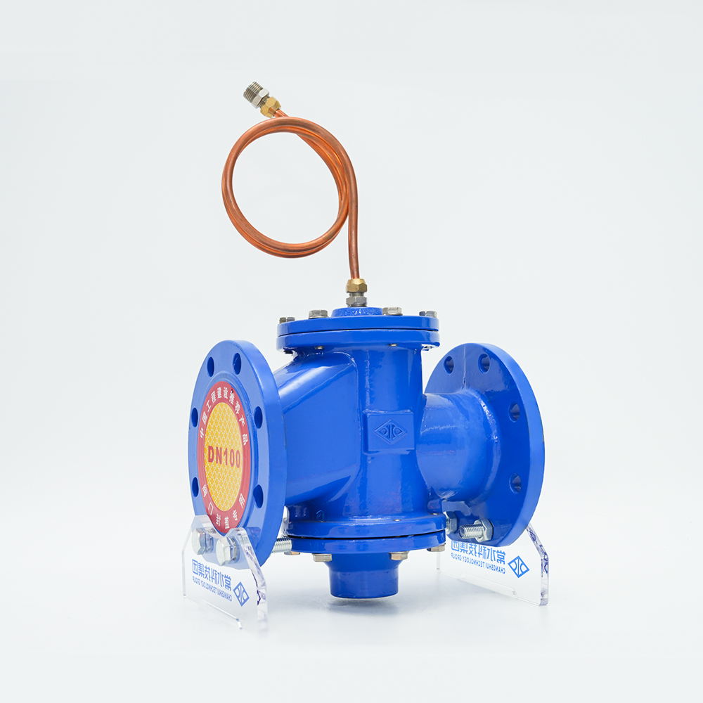
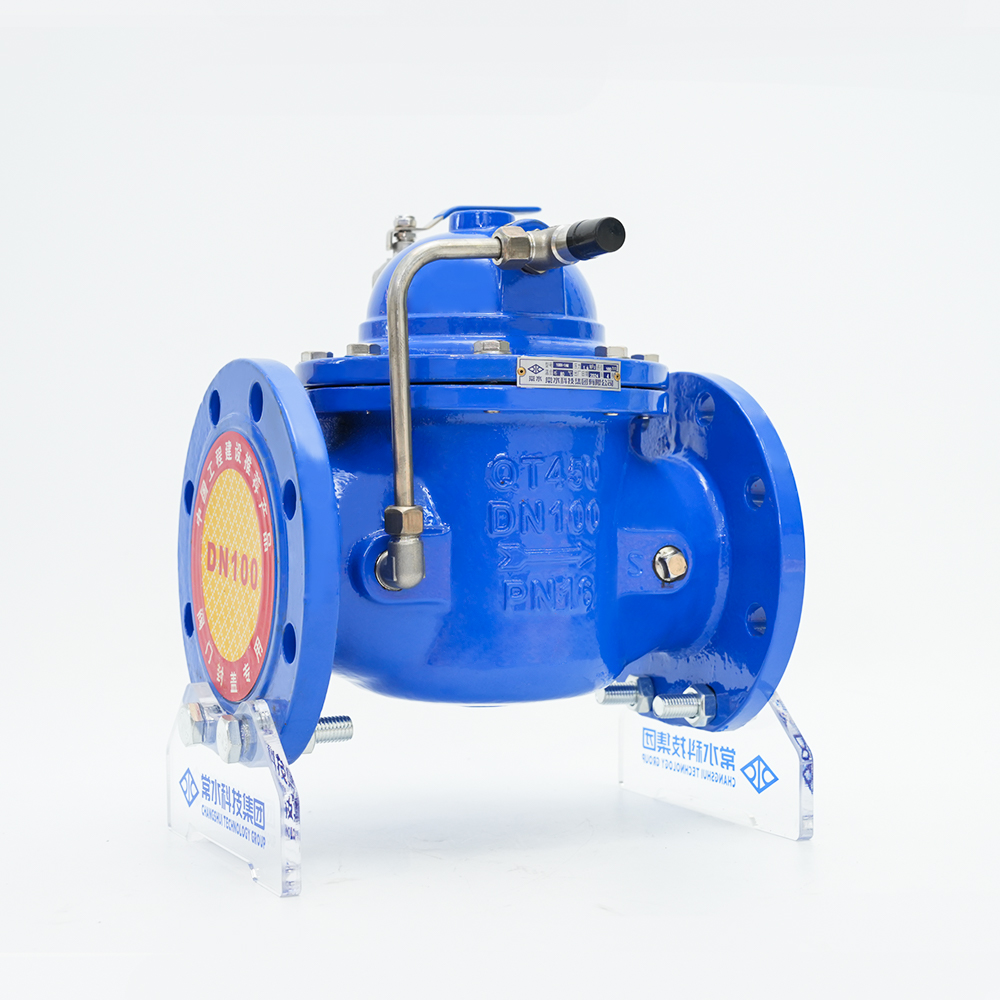
It is also worth separating two jobs that share a name. On the utility side of a plant — pressure sustaining, surge relief and pump protection on water lines — a pilot-operated valve modulates rather than pops and holds upstream pressure steady. That is pipeline and system protection, and it is not a substitute for a UV-stamped device on a pressure vessel.
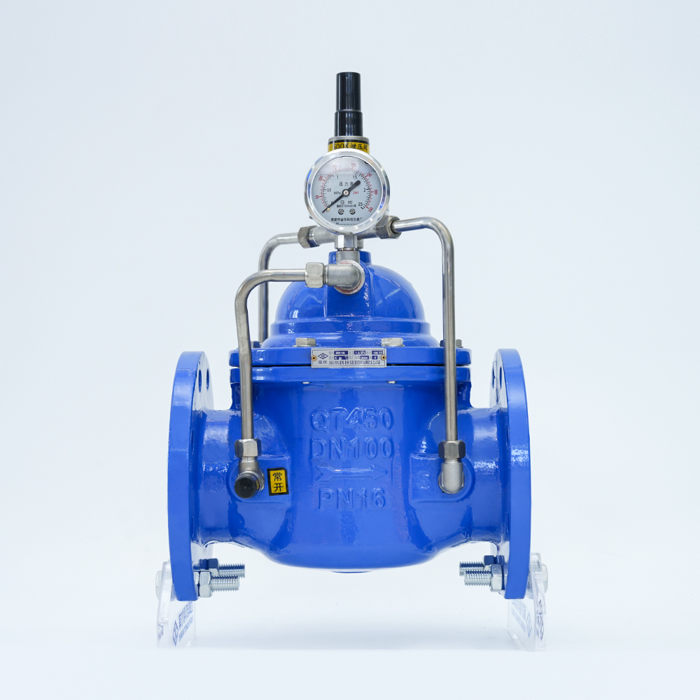 500X-16Q Ductile Iron Pressure Holding and Relief ValvePilot-operated ductile iron valve for water pressure holding and relief in building supply and fire-test circulation, with adjustable pilot setting across DN50–600.View Product →
Where the medium rules out carbon steel, the same logic carries over to the valves around the relief device — isolation, bypass and drain valves in a matching stainless grade, so the line behaves as one material system rather than a patchwork.
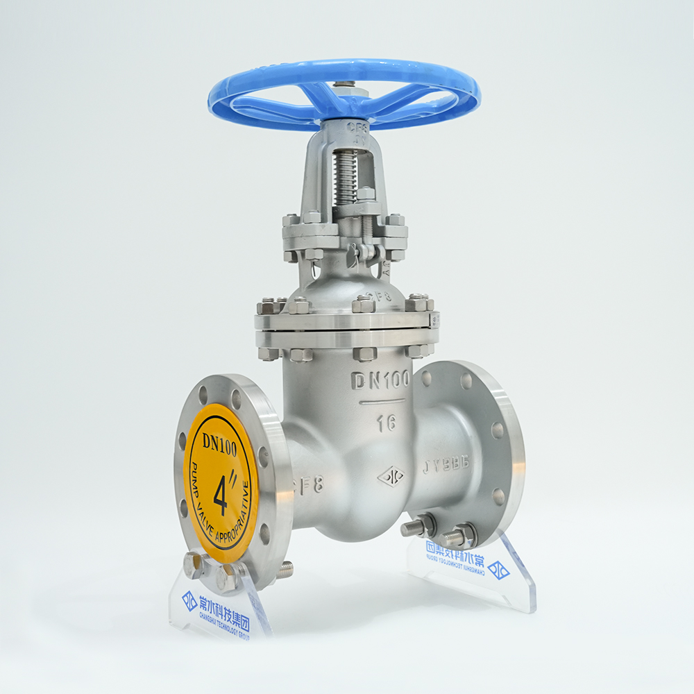 Z41W-16P Stainless Steel Flange Gate ValveStainless steel 304 flanged gate valve for water isolation and bypass lines, with wedge gate, DN15–600 range and multiple pressure ratings.View Product →
Testing, Documentation and Lifecycle
Every ASME valve leaves the works with a set pressure test, a seat tightness test and, where the code requires it, a shell test. The nameplate then carries the stamp, certified capacity, set pressure and relieving temperature, and that data belongs in the vessel file because the next inspection will ask for it.
In our own factory and test floor, relief and control valve assemblies pass bench set-pressure checks and body pressure tests before dispatch, with material certificates kept alongside the batch records. Once in service, the interval between bench tests depends on jurisdiction and on experience with the duty; dirty media and cycling temperatures shorten it considerably.
A Practical Selection Checklist
- Confirm the governing code section from the vessel or boiler data report, not from a process description.
- State the fluid, phase and relieving conditions, including the permitted overpressure.
- Calculate required capacity for blocked outlet, utility failure and fire, then keep the largest figure.
- Choose a certified capacity above that requirement, in a standard orifice size.
- Check built-up back pressure and inlet loss before fixing the body style.
- Specify material, trim and any special testing, and require the certification package with delivery.
None of this is complicated, but all of it is sequential: the wrong section invalidates the stamp, the wrong capacity invalidates the protection, and an unsupported installation invalidates both. Get those three right and the rest of the specification tends to fall into place — and when a clause still reads ambiguously, ask the question before the order rather than after the inspection.