
 中文简体
中文简体 English
 русский
Content
- 1 Why Air Accumulates in a Pressurized Water Line
- 2 How an Air Relief Valve for a Water Line Works
- 3 Comparing the Main Air Valve Configurations
- 4 Sizing, Materials and Standards
- 5 Installation and Isolation
- 6 Water Hammer, Column Separation and Surge Control
- 7 Keeping Pressure Inside the Safe Zone
- 8 Maintenance and Troubleshooting
Trapped air is one of the most common and least visible problems in a water line. It hides at high points, gathers behind closed valves and shows up as noisy pipes, jumping flow meters and pumps that work harder than they should. An air relief valve for a water line deals with all of it automatically, releasing accumulated air while the line is under pressure and letting air back in when the line drains. This guide gathers what we have learned as a valve manufacturer about how these valves work, how to size and install them, and how to keep them reliable.
Why Air Accumulates in a Pressurized Water Line
Hydraulic models rarely show air, yet the air is always there. Some of it enters while the line is filling, some of it comes out of solution when pressure or temperature changes, and some of it is drawn in through a pump suction that runs too shallow. The usual entry points are worth knowing, because each one leads to a different placement and sizing decision.
- Filling and commissioning. As water advances through a new or recently drained main, it compresses the air ahead of it into the highest points of the profile.
- Pump suction vortices. Low submergence or an oversized suction intake lets the pump pull air from the surface of the wet well.
- Air released from solution. Cold water holds more dissolved air than warm water, and a drop in pressure lets that air appear as bubbles.
- Vacuum during draining or shutdown. When a pump stops or a low point is emptied, the water column can separate and create a partial vacuum.
- Column separation after a surge. Rapid valve closure or a pump trip tears the column apart, leaving vapor cavities that collapse moments later.
Once air collects, the consequences multiply. A pocket at a high point reduces the effective cross section of the pipe, so the same flow costs more energy. Bubbles confuse meters, cause erratic pressure readings and trigger unnecessary pump cycling. When a pocket finally breaks loose, it can slam into a bend or a closed valve and produce the pressure spike we call water hammer.
How an Air Relief Valve for a Water Line Works
Inside almost every air valve sits a float, a seat and one or two orifices. With water in the body, the float rises and closes the orifice. When air arrives, the water level drops, the float falls and the air escapes. That simple mechanism supports three distinct jobs, and understanding them is the key to choosing the right valve.
- Continuous air release. A small orifice, usually only a few millimetres across, bleeds off the steady trickle of air that comes out of solution during normal operation, while the line stays at full working pressure.
- Air and vacuum duty. A large orifice opens wide when the line is nearly empty, exhausting the big volume of air during filling and admitting air fast enough to prevent a vacuum when the line drains.
- Combination duty. One body carries both a small and a large orifice, which is why combination valves are the default choice on most municipal and industrial water lines.
The discharge path matters as much as the float. A valve without an anti-slam device can reseat hard when high-velocity air is followed by water, and the resulting shock can crack a body or damage a float. Anti-slam designs throttle that closing action, and they are worth the extra cost wherever flow velocities are high.
Comparing the Main Air Valve Configurations
| Configuration | Primary function | Typical orifice size | Best suited to |
|---|---|---|---|
| Small-orifice air release | Vents small air volumes continuously at full line pressure | 1.5 to 3 mm | Long mains and pump discharge headers |
| Large-orifice air and vacuum | Exhausts and admits large air volumes during filling and draining | 25 to 100 mm | High points and points where vacuum can form |
| Combination, dual orifice | Both functions in a single body | Small plus large | Most municipal water and fire lines |
| Combination with anti-slam device | Combination duty with a throttled closing of the large orifice | Small plus large, throttled | High-velocity lines with a history of surge damage |
Sizing, Materials and Standards
Sizing starts with two numbers: the filling or draining rate that the large orifice must handle, and the volume of dissolved air that the small orifice must vent. Manufacturers publish capacity curves for both, and the large orifice is normally sized so that air velocity through the discharge stays within safe limits. Selecting by pipe size alone is the most common mistake we see in enquiries.
For water service the body is usually ductile iron with a fusion-bonded epoxy coating approved for potable water, while the float, seat and internal trim are stainless steel. Seals are normally EPDM or NBR, depending on water quality and disinfection residual. Pressure ratings of PN10 and PN16 cover most distribution and transmission work, and standards such as AWWA C512 and EN 1074-4 define the performance tests a serious supplier should be able to document. On long-life municipal work it also pays to plan for decades of service, a subject we covered in our notes on how ductile iron valves contribute to municipal water systems.
Installation and Isolation
Placement decides whether an air valve does its job or simply leaks. The classic locations are the highest points of the profile, the discharge side of a pump just after the check valve, long horizontal runs where air can travel, and the upstream side of any valve that isolates a section. On rising mains, an air valve every 300 to 500 metres of horizontal run is common practice.
The discharge should vent to atmosphere above ground where possible, above the local flood level and away from walkways, so that escaping air and the occasional spray create no hazard. Below the air valve, fit an isolation valve so that service work never requires draining the whole main, which turns a full-day job into a twenty-minute one. A resilient-seated gate valve gives bubble-tight shutoff for exactly this duty and holds up well in buried chambers.
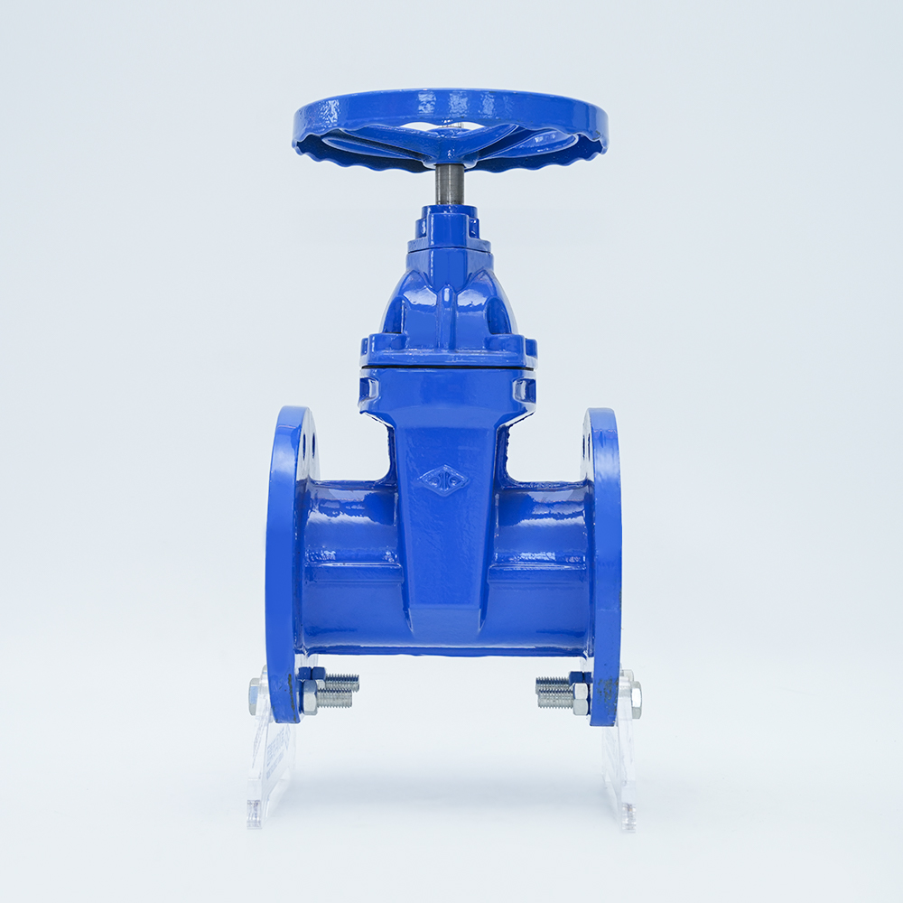 Dark Stem Soft Seal Gate Valve Z45X-16QThe gate valves produced by our factory use the overall rubber coating of the gate plate to produce deformation compensation to achieve a good sealing effect, overcomi...View Product →
Water Hammer, Column Separation and Surge Control
Air valves and surge protection are partners, not alternatives. The air valve prevents vacuum from forming and lets the line refill gently, while the check valve on the pump discharge controls the reverse flow that follows a trip and limits the severity of the surge. On lines that have suffered column separation, we usually recommend a slow-closing or silencer check valve, which damps the closing action and softens the pressure wave travelling back to the pump. Where a line is long and velocities are high, commissioning a surge analysis before the valves are ordered is money well spent.
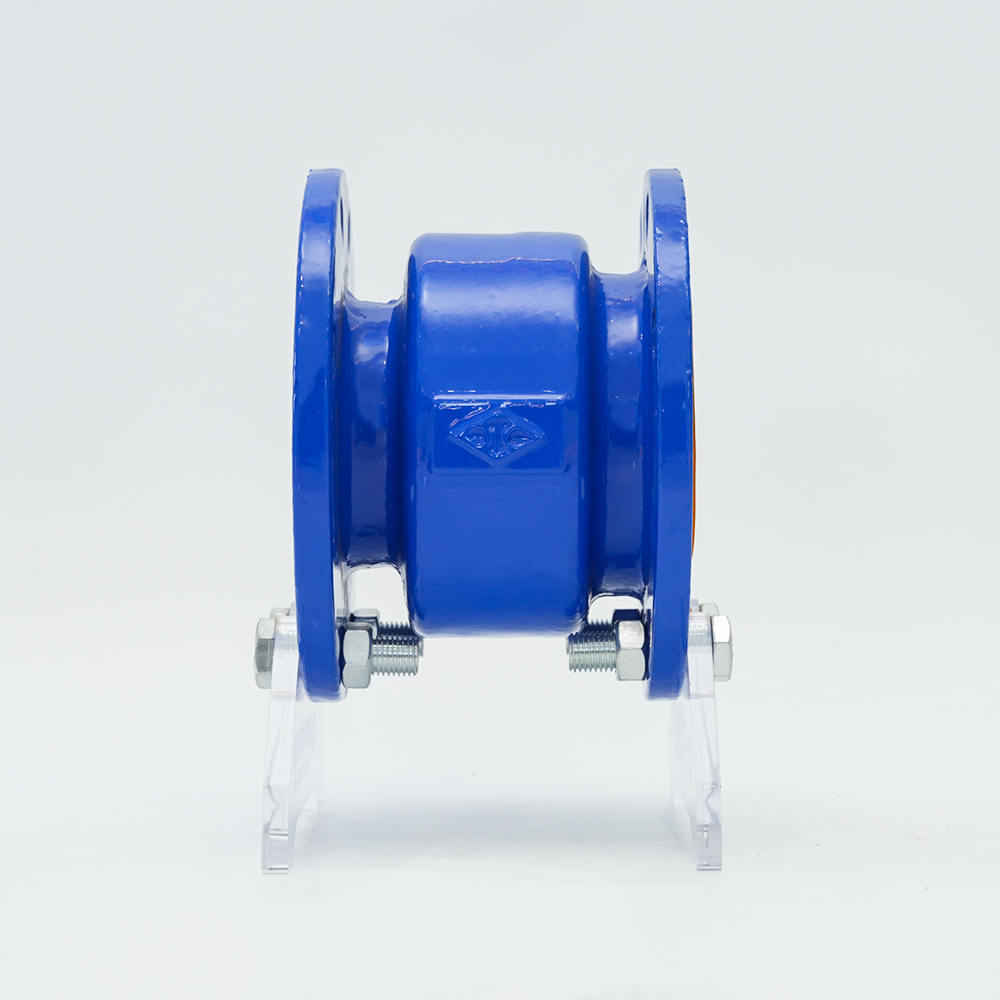 Silencer Check Valve HC41X-16QSilencer check valves are mainly suitable for water supply and drainage systems of high-rise buildings, fire pipe water supply systems, etc. This silencer check valve ...View Product →
Keeping Pressure Inside the Safe Zone
Once air is under control, the next risk on a long water line is overpressure. Sustaining and relief valves hold a minimum upstream pressure for the system downstream and discharge excess pressure when it climbs, while pressure reducing valves keep a distribution zone at a steady head. They often sit in the same chamber as the air valve, sharing the isolation valve and drainage arrangement, so specifying pressure rating, set point and relief capacity together with the air valve duty avoids difficult retrofits later.
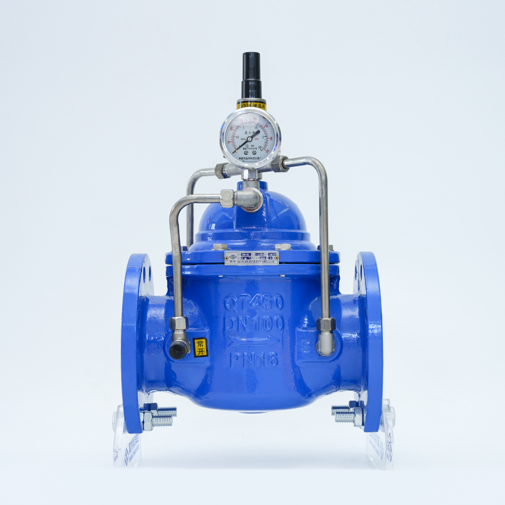 Safety Pressure Holding/Pressure Relief Valve 500X-16QThe pressure-maintaining pressure relief valve consists of a main valve and an external control pilot valve. It is mainly installed in the bypass of the protected wate...View Product →
Maintenance and Troubleshooting
An air valve is a low-maintenance device, but not a maintenance-free one. The small orifice usually fails first, because scale, iron deposits and biofilm easily block an opening only a couple of millimetres wide. A valve that has stopped venting is often not broken, just dirty.
A simple annual routine
- Inspect the valve at least once a year, and more often on raw or aggressive water.
- Isolate it, remove the bonnet, then clean the orifice and seat with a soft brush.
- Check the float for dents, corrosion or water ingress, and renew the seals.
- Confirm free float movement, then reopen the isolation valve slowly and check for leaks.
- Record every fault, because recurring blockage usually points to a water quality problem upstream.
In freezing climates, protect both the body and the discharge from ice, and never plug a discharge to stop a drip, since a blocked discharge turns a minor leak into a pressure problem.
Air relief valves are small, inexpensive and easy to overlook, yet they decide how quietly, efficiently and safely a water line runs. Get the sizing, the venting height and the isolation arrangement right, and the rest of the system becomes far easier to operate.
Changshui Technology Group Co., Ltd. designs and manufactures valves for building, heating, water supply, fire protection, petroleum, chemical and power applications, from ductile iron and cast steel to stainless steel, fluorine-lined and copper ranges. Every batch passes through our own laboratory, where ultrasonic testing, material testing, torque measurement and valve test benches are part of routine quality control. If you are specifying an air valve installation and want to talk through the isolation valve, check valve or pressure control that goes with it, our engineers are glad to help. A good place to start is our valve range and manufacturing process.