
 中文简体
中文简体 English
 русский
Content
- 1 What Is Valve Leak Testing and Why Does It Matter?
- 2 Shell Test vs. Seat Leak Test: Two Types of Leakage
- 3 Hydrostatic vs. Pneumatic Leak Testing: Choosing the Right Medium
- 4 Key Leak Testing Standards: API 598, ISO 5208, and Beyond
- 5 Step-by-Step Valve Leak Testing Procedure
- 6 Common Mistakes and Misconceptions in Valve Leak Testing
- 7 How Valve Leak Testing Affects Valve Quality and Supplier Selection
- 8 Conclusion: Building Confidence Through Rigorous Leak Testing
When you specify a valve for a critical process line, the difference between a reliable shutdown and a hazardous crossover often comes down to a few milliliters of leakage per minute. Valve leak testing is the systematic verification that a valve can contain the process fluid under pressure—both from escaping to the atmosphere and from passing through the closed closure element. This guide explains the two fundamental leak paths, the test methods used in manufacturing and maintenance, the key industry standards you will encounter in technical specifications, and how to use this knowledge to evaluate a supplier's quality assurance program.
What Is Valve Leak Testing and Why Does It Matter?
Valve leak testing is the controlled application of a test medium to a valve to verify the integrity of its pressure boundary and the effectiveness of its closure mechanism. It is performed to confirm that a valve meets metallurgical soundness, manufacturing quality, and functional performance requirements before it enters service.
Leakage in a valve falls into one of two categories:
- External leakage—medium escaping from the valve interior to the surrounding environment through the body, bonnet, stem seals, or joint gaskets. This type is always unacceptable in any quantity.
- Internal leakage—medium passing from the high-pressure side to the low-pressure side through the closed closure element (disc, ball, gate, or plug). This type is governed by acceptance limits that vary by valve type, sealing material, and the governing standard.
Uncontrolled leakage has direct operational consequences. A leaking isolation valve in a heat exchanger train forces unscheduled plant shutdowns. A passing steam valve wastes energy continuously. In hydrocarbon or toxic media service, either leak path becomes a personnel safety and environmental compliance issue. For these reasons, leak testing is not a formality—it is the primary quality gate between a valve's design and its field deployment. The API 598 and ISO 5208 standards define the test procedures and acceptance criteria most commonly referenced in valve specifications worldwide.
Shell Test vs. Seat Leak Test: Two Types of Leakage
Manufacturers and inspection personnel evaluate the two leak paths independently, in a fixed sequence, and against different acceptance criteria.
Shell Test (Pressure Boundary Integrity)
The shell test, also called a body test, verifies that the valve's pressure-containing parts—the body, bonnet, and their joints—can withstand elevated pressure without visible external leakage. Water is the typical test medium. The test pressure is usually 1.5 times the valve's rated pressure at the specified temperature, in accordance with API 598. The acceptance criterion is unambiguous: no visible leakage is permitted. Any weeping, sweating, or droplet formation on the external surfaces constitutes failure. Large and high-pressure valves require proportionally longer hold times to allow pressure stabilization and reveal slow seepage.
Seat Leak Test (Closure Element Tightness)
The seat leak test verifies the sealing effectiveness of the closed closure element against the seat rings. This is where "zero leak" claims must be scrutinized. The acceptable leakage rate depends on three factors:
- Valve type—gate valves and ball valves generally achieve tighter shutoff than butterfly valves with similar sealing materials.
- Sealing material—elastomeric seats (EPDM, PTFE, nitrile) can meet essentially zero leakage under API 598 soft-seat criteria, while metal-to-metal seats permit small but measurable leakage rates.
- Governing standard—API 598 specifies maximum allowable leakage for each valve type and nominal size; ISO 5208 provides a broader set of rate classes that the purchaser can select.
The shell test must be completed and accepted before the seat leak test begins, because a defect in the pressure boundary would invalidate any subsequent measurement of internal leakage. For an example of how sealing integrity affects a specific product family, consider slow-closing check valve designs, where seat leakage directly impacts backflow prevention and water hammer control in pumping systems.
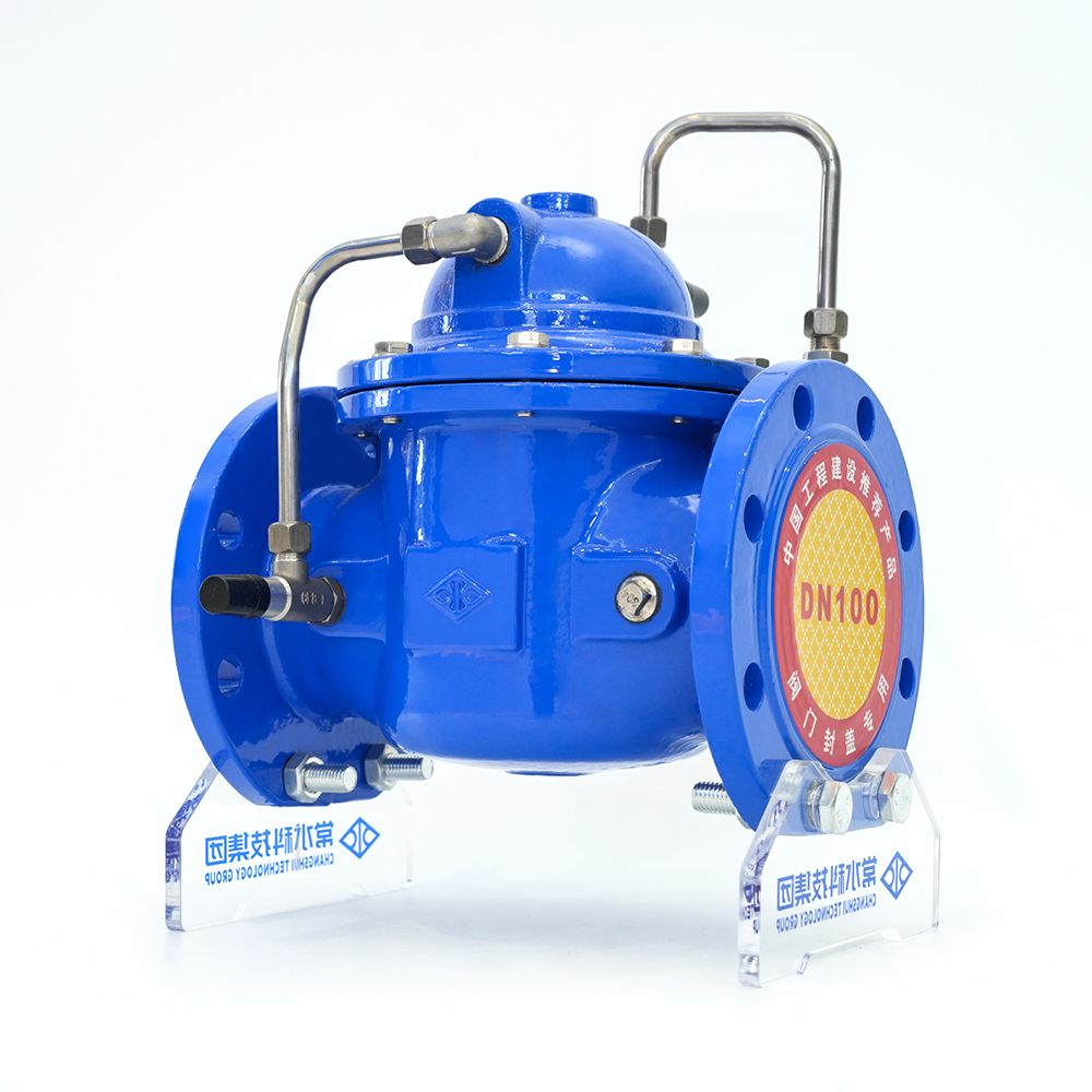 Ductile Iron Slow Closing Check Valve 300X-16Q Suppliers, OEM/ODM Company - ChanChangshui is China custom Ductile Iron Slow Closing Check Valve 300X-16Q suppliers and OEM/ODM Slow Closing Check Valve 300X-16Q company,...View Product →
Hydrostatic vs. Pneumatic Leak Testing: Choosing the Right Medium
The choice of test medium—liquid or gas—has a decisive impact on safety, sensitivity, and test practicality. Neither method is universally superior; the correct selection depends on the valve's service condition, the required leak detection threshold, and the test environment.
| Parameter | Hydrostatic Testing | Pneumatic Testing |
|---|---|---|
| Typical medium | Water, sometimes with anti-corrosion additives | Air, nitrogen, or inert gas |
| Leak detection sensitivity | Moderate; liquid flow visible at larger orifices | High; gas escapes through micro-passages and is detectable with soap solution |
| Safety risk | Low; stored energy is minimal due to fluid incompressibility | High; compressed gas stores significant energy; failure can be explosive |
| Test pressure practice | Typically 1.5 × rated pressure | Typically 1.1 × rated pressure or lower, per procedural safeguards |
| Primary application | Factory shell and seat testing for most industrial valves | Oxygen service, clean dry gas systems, and where residual liquid is prohibited |
For most valve types in water, steam, oil, and gas pipelines, hydrostatic testing is the preferred factory method. Water is inexpensive, safe, and easily disposed. The primary drawback is the need to dry and protect the valve internals after testing, particularly for carbon steel and ductile iron bodies. Pneumatic testing is reserved for services where moisture contamination cannot be tolerated—such as oxygen supply lines, high-purity gas systems, or cryogenic applications. If pneumatic testing is required, you should ensure the test area is barricaded, personnel are excluded, and pressure is raised gradually with a regulated supply. The higher sensitivity of gas testing also makes it the method of choice for detecting very small seat leaks in helium mass spectrometry applications, although such methods are typically used for specialized valves rather than standard industrial products.
Key Leak Testing Standards: API 598, ISO 5208, and Beyond
Understanding the hierarchy of leak testing standards helps you specify the correct test for your application and also enables you to ask a supplier the right questions about their factory test procedures. These standards differ in scope, test pressure, hold times, and leakage classifications.
API 598 — Valve Inspection and Test
API 598 is the most widely used standard for inspection and testing of isolation valves—gate, globe, ball, check, and butterfly valves. It specifies test pressures (1.5× rating for shell, 1.1× for seat), hold durations, and leakage rate tables. For soft-seated valves, API 598 requires essentially zero leakage. For metal-seated valves, a small allowable leakage rate is permitted, based on valve size and type.
ISO 5208 — Industrial Valves: Pressure Testing
ISO 5208 introduces a more granular classification system with leakage rates designated from Rate A (no detectable leakage) through Rate F and beyond. This flexibility allows a purchaser to select a leakage rate that matches their service requirement, rather than accepting a single default. For example, Rate A is specified for high-integrity isolation, whereas Rate D or E may be acceptable for non-critical services where a slight seat weep can be tolerated. The rate must be explicitly agreed upon and written into the purchase specification.
ASME B16.34 — Valves: Flanged, Threaded, and Welded End
ASME B16.34 primarily defines the pressure-temperature ratings and dimensional standards for flanged and threaded valves. It contains requirements for shell testing, but it does not provide comprehensive seat leakage acceptance tables. Therefore, when a specification cites ASME B16.34, the seat leak test criteria are usually drawn from API 598 or ISO 5208 as incorporated into the project specification.
MSS SP-61 — Hydrostatic Testing of Steel Valves
MSS SP-61 is a long-established test standard for steel valves. Its scope is similar to API 598, A slight differences exist in hold times and acceptance criteria when compared directly against API 598. In practice, API 598 has superseded MSS SP-61 in most modern specifications, but you may still encounter MSS SP-61 in legacy project documentation.
ANSI FCI 70-2 — Control Valve Seat Leakage
ANSI FCI 70-2 (also known as IEC 60534-4) applies to control valves rather than isolation valves. It defines six leakage classes (Class I through VI) that correspond to different sealing constructions, from Class I (metal seat with no specified test) to Class VI (soft seat with essentially zero leakage). If you are specifying a modulating valve, this standard replaces API 598 as the governing seat leakage specification.
When selecting the applicable standard, consider the valve type (isolation vs. control), the industry sector (refining, water, chemical, power), and the buyer's project specification. For flanged ball valves in API 598 applications, the seat leak test is a mandatory factory acceptance step that validates the sealing performance expected by the purchaser.
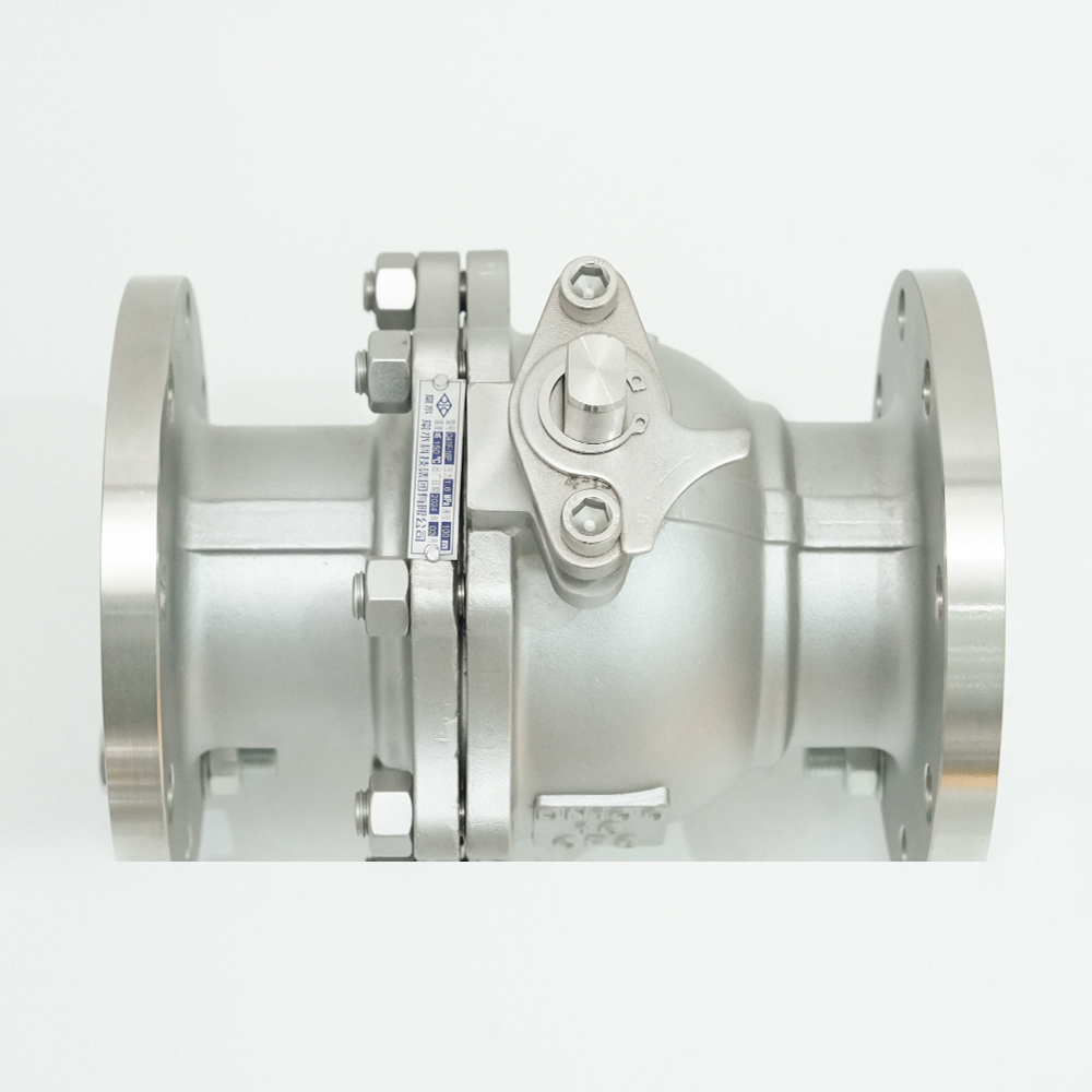 Stainless Steel Flange Ball Valve Q41F-16P Suppliers, OEM/ODM Company - ChangshuChangshui is China custom Stainless Steel Flange Ball Valve Q41F-16P suppliers and OEM/ODM Stainless Steel Flange Ball Valve Q41F-16P com...View Product →
Step-by-Step Valve Leak Testing Procedure
A standard factory leak test follows a logical sequence that maximizes the probability of detecting defects while minimizing the risk of damaging the valve. The following steps reflect common industry practice for hydrostatic testing:
- Prepare the valve. Remove all foreign material, scale, dirt, and machining chips from the valve interior. Clean the sealing surfaces carefully. Confirm that the valve is in the fully closed position.
- Mount and fill. Attach the valve to the test fixture with blanks or plugs on the open flanges. Fill the valve cavity completely with the test medium, ensuring that all air is vented from the highest point.
- Shell test. Pressurize the valve to the prescribed value (typically 1.5× the rated pressure). Hold for the required duration—API 598 specifies hold times ranging from 15 seconds for small valves (DN ≤ 50) to 120 seconds for large valves (DN ≥ 600). Visually inspect the entire external surface including body, bonnet, and stem seal areas. Any visible leakage is grounds for rejection.
- Depressurize and prepare for seat test. Vent the pressure, then orient the valve such that the closure element is positioned to receive the test medium from the required side. For bidirectional valves, the manufacturer may perform the seat test in one direction if the design does not have a preferred seating direction.
- Seat leak test. Re-pressurize the valve to the seat test pressure (typically 1.1× the rated pressure). For soft-seated valves, the acceptance criterion is no visible leakage. For metal-seated valves, collect the leakage through the downstream vent and measure it against the allowable rate from the governing standard.
- Record the results. Document the test medium, test pressure, hold time, observed leakage, ambient temperature, and the name of the operator. This record is the foundation for the factory test certificate.
- Post-test handling. Drain the test medium, dry the valve cavity, and apply corrosion protection where required. For valves with elastomeric seats, ensure that any residual water does not remain in contact with the sealing material for extended periods.
Common Mistakes and Misconceptions in Valve Leak Testing
Even with a well-written procedure, certain recurring errors can undermine the validity of a leak test. Awareness of these pitfalls helps both manufacturers and inspectors maintain test integrity.
Shortening the Hold Time to Accelerate Production
A brief test of a few seconds may reveal an obvious flood, but it cannot reliably expose a slow seep through a small crack or imperfect seat. The hold times specified in API 598 and ISO 5208 exist to allow pressure to stabilize and micro-leaks to become visible. Deviation from the specified duration should be treated as a process failure, not a production efficiency improvement.
Confusing Test Medium Sensitivity with Service Conditions
Hydrostatic testing with water is less sensitive than pneumatic testing when performed at similar pressures, because water's higher viscosity and surface tension resist flow through microscopic passages. This does not make hydrostatic testing wrong—it is the correct method for most factory tests—but it does mean that a valve that passes an air test at low pressure may still fail a hydrostatic test at high pressure, and vice versa. The test medium must match the risk profile and service application.
Testing Without Cleaning the Sealing Surfaces
Grit, machining debris, or scale on a valve seat can mask a leak path, yielding a false "pass" result that disappears only after the valve is in service and the debris is swept away. Cleaning the internal surfaces and sealing faces is a mandatory prerequisite, not an optional step.
Ignoring the Distinction Between Shell and Seat Tests
A valve that passes a shell test has not been qualified for seat tightness, and a valve that passes a seat test at low pressure has not proven the integrity of its pressure boundary. Each test verifies a different property and has its own acceptance threshold.
Overlooking Temperature Effects on Test Pressure
Hydrostatic test pressures are established for a reference temperature. If the test liquid heats up during the test—through pumping energy or ambient conditions—the pressure may rise above the intended value. Conversely, a cooling liquid can cause the displayed pressure to drop, leading to a false failure. Allow the system to stabilize before recording the pressure.
How Valve Leak Testing Affects Valve Quality and Supplier Selection
The rigor of a manufacturer's leak testing program is a direct indicator of their overall quality culture. A supplier that performs tests in accordance with a recognized standard, documents the results completely, and can explain their acceptance criteria is likely to apply the same rigor to materials selection, machining, and assembly.
When evaluating a valve manufacturer, you should ask for more than a generic statement of "tested per API 598." A credible factory test report includes:
- The specific standard (API 598, ISO 5208) and the edition referenced;
- The test pressure applied and the hold time for both shell and seat tests;
- The measured leakage rate for the seat test, rather than just a "pass/fail" notation;
- The test medium and the ambient temperature during testing;
- The operator's identification and the date of test.
Manufacturers with in-house metallurgical laboratories, dedicated valve test benches, and spectrochemical analysis equipment typically have tighter process control than those who outsource testing. This is a practical point for purchasers. When you assess a potential supplier's ductile iron valve range, ask how their factory testing protocol works, what leakage rates they hold for standard stock, and whether you can witness the test during a factory acceptance visit. A reputable manufacturer will welcome such scrutiny.
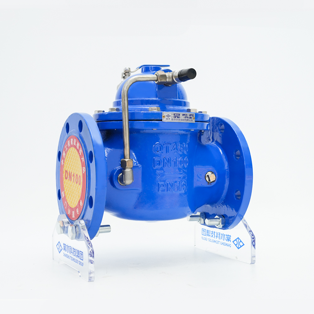 Ductile Iron Valves Manufacturers, Cast Iron Valve FactoryChangshui Technology Group Co., Ltd. is China Ductile Iron Valves Manufacturers and Cast Iron Valve Factory, we offer Custom Ductile Iron...View Product →
Conclusion: Building Confidence Through Rigorous Leak Testing
Valve leak testing is the practical bridge between a valve's design and its dependable performance in the field. The distinction between external leakage (shell test) and internal leakage (seat test) is fundamental, and the choice of test medium—hydrostatic vs. pneumatic—must match the service requirements and safety constraints of the application. The standards you will encounter most often—API 598, ISO 5208, ASME B16.34, MSS SP-61, and ANSI FCI 70-2—each play a distinct role in governing test procedures and acceptance criteria.
Testing does not end at the factory gate. Valves installed in critical services should be re-tested periodically as part of a preventive maintenance program, particularly after repair or disassembly. The same principles of clean sealing surfaces, correct test pressure, and documented acceptance criteria apply in the workshop environment as they do on the production floor.
When you procure valves, use leak testing knowledge as part of your supplier evaluation lens. Request clear testing documentation, verify that the stated acceptance criteria align with your service needs, and remain attentive to the quality signals that a manufacturer's test program provides. A valve that has passed a well-executed leak test is a valve you can trust with the safety of your people and the continuity of your process.