
 中文简体
中文简体 English
 русский
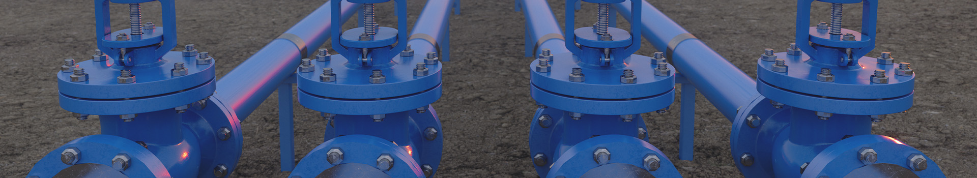
Content
- 1 What Is a Swing Check Valve and How It Works
- 2 Pre-Installation Checklist
- 3 Step-by-Step Swing Check Valve Installation Guide
- 3.1 Step 1 — Identify the Correct Flow Direction
- 3.2 Step 2 — Determine the Correct Installation Orientation
- 3.3 Step 3 — Position and Support the Valve
- 3.4 Step 4 — Install Gaskets and Insert Flange Bolts
- 3.5 Step 5 — Tighten Flange Bolts in Cross Pattern
- 3.6 Step 6 — Remove Temporary Supports and Check Clearances
- 4 Common Installation Mistakes to Avoid
- 5 Post-Installation Testing and Commissioning
- 6 Maintenance Tips to Extend Service Life
What Is a Swing Check Valve and How It Works
A swing check valve is a one-way valve that uses a hinged disc — often called a clapper — to allow fluid to flow in a single direction and automatically block reverse flow. When forward pressure pushes fluid through the valve, the disc swings open. When flow stops or reverses, the disc swings back against the seat under gravity and backpressure, sealing the line.
Unlike spring-loaded or ball check valves, the swing type relies on the momentum of the disc rather than a spring force. This makes it especially well-suited for low-velocity, high-volume flow applications such as water supply mains, pump discharge lines, and fire protection systems. The simplicity of the mechanism also means lower pressure drop compared to most other check valve designs.
Common materials include ductile iron, cast steel, and stainless steel. Ductile iron check valves are the most widely used in water supply and drainage applications due to their combination of strength, corrosion resistance, and cost-effectiveness. For aggressive chemical or high-temperature environments, cast steel check valves offer superior pressure and temperature ratings.
Pre-Installation Checklist
Proper preparation before installation prevents the majority of performance failures. Before placing a swing check valve into service, verify each of the following:
Confirm Valve Specifications Match the Application
Check that the valve's pressure class (PN rating or ANSI class), nominal diameter (DN), and end connection type match your pipeline requirements. The table below summarizes common rating combinations used in water and industrial systems:
| Application | Recommended Pressure Class | Typical Pipe Size Range | Suggested Material |
|---|---|---|---|
| Municipal water supply | PN10 / PN16 | DN50 – DN600 | Ductile iron |
| Pump discharge lines | PN16 / PN25 | DN50 – DN400 | Ductile iron / Cast steel |
| Industrial process lines | PN25 / Class 150 | DN25 – DN300 | Stainless steel / Cast steel |
| Fire protection systems | PN16 | DN65 – DN300 | Ductile iron |
Inspect the Valve Before Installation
- Remove all shipping plugs, protective caps, and packing materials from the valve body and flanges.
- Visually inspect the disc, hinge pin, and seat ring for any casting defects, cracks, or transport damage.
- Manually operate the disc (if accessible) to confirm it swings freely without binding.
- Confirm that the sealing surface (disc face and seat) is clean and free of debris.
Prepare the Pipeline
- Flush the upstream pipeline to remove weld slag, scale, and debris before installing the valve.
- Verify that the mating flanges are parallel, aligned, and at the correct face-to-face distance.
- Select compatible gaskets — typically rubber flat gaskets for PN16 flanged valves in water service.
Step-by-Step Swing Check Valve Installation Guide
Step 1 — Identify the Correct Flow Direction
This is the single most important step. A swing check valve installed backwards will block flow entirely. Always locate the flow direction arrow cast or stamped on the valve body and confirm it aligns with the intended flow direction in your pipeline before proceeding.
If the arrow is unclear, you can identify flow direction by opening the valve bonnet (where accessible) and noting the orientation of the hinge — the disc should swing open in the direction of forward flow, with the hinge at the top of the disc.
Step 2 — Determine the Correct Installation Orientation
Swing check valves are designed primarily for horizontal pipe installation, with the hinge pin in the horizontal position and the disc hanging vertically. This orientation ensures gravity assists closure when flow stops.
Vertical installation is possible — but only when the flow direction is upward. In a vertical downflow configuration, the disc will not close reliably under gravity and the valve should not be used. If vertical downflow protection is required, a lift check valve or spring-loaded check valve is a more appropriate choice.
Step 3 — Position and Support the Valve
For valves DN200 and larger, use appropriate rigging to position the valve between the flanges — do not allow the full weight of the valve to rest on the flange bolts. Install temporary supports or valve hangers as needed. Confirm the valve centerline is coaxial with the pipeline before tightening any fasteners.
Step 4 — Install Gaskets and Insert Flange Bolts
Place one gasket on each flange face, ensuring it is centered and not overlapping the flow bore. Insert all flange bolts finger-tight before applying any torque. Use the correct bolt grade specified for the pressure class — for PN16 flanged valves, Grade 4.6 or 8.8 carbon steel studs are standard.
Step 5 — Tighten Flange Bolts in Cross Pattern
Tighten the bolts progressively in a cross (star) pattern in at least three passes to ensure even gasket compression and prevent flange distortion. Final torque values depend on bolt size and gasket type — refer to the manufacturer's installation drawing for specific values. As a general reference:
- M16 bolts: 60 – 80 Nm
- M20 bolts: 120 – 160 Nm
- M24 bolts: 200 – 260 Nm
Do not exceed the maximum recommended torque, as over-tightening can damage the gasket and distort the valve body.
Step 6 — Remove Temporary Supports and Check Clearances
Once the valve is fully bolted, remove any temporary installation supports. Confirm there is sufficient clearance above the valve body for the bonnet cover to be removed during future maintenance. For swing check valves with an external lever and weight (used to assist closing speed), verify the lever moves freely without contacting adjacent piping or structure.
Common Installation Mistakes to Avoid
Even experienced technicians encounter installation errors that lead to early valve failure or system damage. The following mistakes account for the majority of swing check valve problems reported in the field:
Installing Too Close to Upstream Disturbances
Elbows, reducers, pumps, and partially open gate valves create turbulent flow that causes the check valve disc to flutter — opening and slamming shut repeatedly. This accelerates wear on the hinge pin and seat, and produces water hammer. Maintain a minimum straight pipe length of 5 times the nominal pipe diameter upstream of the check valve wherever possible.
Incorrect Orientation on Vertical Pipes
Installing a swing check valve on a vertical downflow line is a very common mistake. In this position, the disc stays open under gravity regardless of flow, providing no backflow protection whatsoever. Always use valve type specifically rated for the intended installation orientation.
Neglecting Pipeline Flushing
Weld slag, pipe scale, and construction debris are the leading causes of seat damage in newly commissioned systems. Even a small piece of debris caught between the disc and seat will prevent full closure and result in continuous leakage. Always flush upstream piping before installing the valve, or install a temporary strainer upstream during commissioning.
Using Mismatched or Damaged Gaskets
Re-using old gaskets or using gaskets of the wrong material or thickness is a common cause of flange leakage. Always use new gaskets rated for the operating pressure, temperature, and fluid medium. For potable water service, use EPDM gaskets that comply with applicable drinking water standards.
Ignoring the Minimum Flow Velocity Requirement
Swing check valves require a minimum flow velocity to hold the disc fully open. If the operating velocity is too low, the disc will partially close and flutter continuously. As a rule of thumb, the minimum velocity to hold a swing check valve fully open is approximately 0.9 to 1.2 m/s for water service. For applications with frequent low-flow conditions, consider a spring-assisted or dual-plate check valve instead.
Post-Installation Testing and Commissioning
After completing the physical installation, a structured commissioning procedure confirms the valve is sealing correctly and the pipeline is ready for service.
Hydrostatic Pressure Test
Conduct a hydrostatic shell test at 1.5 times the rated working pressure for a minimum of 30 minutes. Inspect all bolted joints and the valve body for leakage. Then perform a seat leakage test by pressurizing the downstream side to the rated working pressure — the upstream side should show no pressure rise if the disc is sealing correctly.
Functional Flow Test
Once the system is pressurized with the operating fluid, start the upstream pump or open the supply valve slowly. Confirm that flow passes freely through the check valve and that no unusual noise (chattering, hammering) is present during steady-state operation. Then shut down the pump and listen for any indication of reverse flow — a correctly functioning swing check valve should close cleanly with minimal water hammer.
Bolt Re-Torque After Initial Pressurization
Gaskets compress slightly once initial system pressure is applied. After the first pressurization cycle, re-torque all flange bolts to the specified values while the system is depressurized. This step is frequently skipped but is important for maintaining long-term joint integrity.
Maintenance Tips to Extend Service Life
Swing check valves are largely maintenance-free during normal operation, but periodic inspection prevents unexpected failures. The following practices significantly extend service life:
- Annual inspection: Remove the bonnet cover and inspect the disc, hinge pin, and seat for wear, erosion, or corrosion. Replace any worn elastomeric seat rings before they cause leakage.
- Hinge pin lubrication: For valves with accessible hinge pins, apply a food-grade or system-compatible grease annually to prevent seizing — especially important in valves that operate infrequently.
- Monitor for water hammer: Persistent water hammer after pump shutoff indicates the disc is closing too slowly. External lever and weight kits are available for most swing check valves and can be added to assist and speed up disc closure.
- Check flange bolts: In high-cycle or vibration-prone systems, inspect flange bolt torque every 12 months and re-torque as needed.
- Replace rather than repair heavily worn valves: When the seat ring or disc face shows significant erosion, full valve replacement is often more cost-effective than seat machining, particularly for PN16-rated ductile iron check valves in standard water service sizes.
For systems where downtime is critical, keeping one spare valve of each installed size in stock eliminates extended outages caused by unexpected valve failure. For corrosive media, acid cleaning, or high-purity applications, review the stainless steel check valve range for material options better suited to those conditions.


