
 中文简体
中文简体 English
 русский
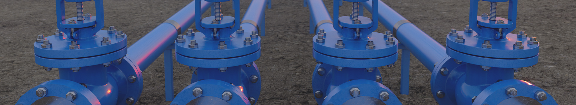
Content
- 1 Check Valve vs Globe Valve: Key Differences Explained
- 2 How Each Valve Works
- 3 Side-by-Side Comparison
- 4 Pressure Drop and Flow Resistance
- 5 Installation and Orientation Requirements
- 6 Material and Temperature/Pressure Ratings
- 7 Common Application Scenarios
- 8 Can Check Valves and Globe Valves Be Used Together?
- 9 Maintenance and Failure Modes
Check Valve vs Globe Valve: Key Differences Explained
Check valves and globe valves serve fundamentally different purposes in a piping system. A check valve allows flow in only one direction and prevents backflow automatically, while a globe valve is a manually or actuator-operated device used to throttle or shut off flow. Choosing the wrong type can lead to system inefficiency, equipment damage, or safety hazards.
Both are found across water treatment, oil and gas, HVAC, chemical processing, and power generation industries—but their operating principles, installation requirements, and maintenance demands differ considerably.
How Each Valve Works
Check Valve Operation
A check valve operates automatically using the pressure differential across its disc or ball. When upstream pressure exceeds downstream pressure, the valve opens and allows flow. When the differential reverses—due to pump shutdown, gravity, or system pressure changes—the valve closes instantly to prevent reverse flow. No external actuator or operator is needed.
Common check valve designs include:
- Swing check valves — disc hinges on a pin; suitable for horizontal pipelines with moderate flow rates
- Lift check valves — disc moves vertically; handles higher pressures and is often used alongside globe valves
- Dual plate (wafer) check valves — compact, spring-assisted; preferred in space-constrained installations
- Ball check valves — ideal for slurries and viscous fluids
Globe Valve Operation
A globe valve uses a movable disc or plug that presses against a stationary ring seat inside a spherical body. Turning the handwheel or actuator stem raises or lowers the disc, changing the flow area and allowing precise throttling. Globe valves can be fully opened, fully closed, or positioned anywhere in between.
The internal S-shaped or Z-shaped flow path creates a higher pressure drop compared to gate or ball valves, but this characteristic makes globe valves excellent for flow regulation applications where precision matters more than minimal resistance.
Side-by-Side Comparison
| Parameter | Check Valve | Globe Valve |
|---|---|---|
| Primary Function | Prevent backflow | Regulate or shut off flow |
| Operation | Automatic (pressure-driven) | Manual or actuated |
| Flow Direction | One-way only | Bidirectional (when open) |
| Throttling Capability | None | Excellent |
| Pressure Drop | Low to moderate | Moderate to high |
| Installation Orientation | Type-dependent (some horizontal only) | Flexible; vertical stem preferred |
| Maintenance Frequency | Low | Medium |
| Typical Applications | Pump outlets, boiler feedlines | Steam lines, coolant loops, process control |
Pressure Drop and Flow Resistance
Pressure drop is one of the most critical selection criteria in valve engineering. Check valves, especially swing and dual-plate types, are designed for minimal resistance in the open position—typical cracking pressures range from 0.5 to 5 psi depending on design, with overall pressure drop often below 1–2 psi at rated flow velocity.
Globe valves, by contrast, have a tortuous internal flow path that intentionally introduces resistance. This is what enables fine throttling control—but it also means pressure drops of 5 to 20 psi or more at full open position are common. In high-flow or energy-sensitive systems, this can translate into measurable pump energy losses over time.
For systems where energy efficiency is a priority and flow control is not required, check valves are the lower-resistance choice. Where precise flow modulation is needed, the higher pressure drop of a globe valve is an acceptable trade-off.
Installation and Orientation Requirements
Installation orientation is a critical factor for check valves. Swing check valves must be installed in horizontal pipelines (or vertical pipelines with upward flow) to ensure the disc closes reliably under gravity. Installing them in vertical downward-flow lines can cause the disc to remain open and fail to prevent backflow.
Lift check valves can function in both horizontal and vertical (upward flow) orientations. Dual-plate wafer check valves are among the most orientation-flexible designs and are commonly used in space-constrained pipework.
Globe valves are more forgiving in terms of orientation. They can be installed horizontally or vertically, although vertical installation with an upward-facing stem is generally preferred to avoid sediment accumulation in the bonnet area and to facilitate easier maintenance access. Flow direction must follow the arrow marked on the body for proper seating and sealing.
Material and Temperature/Pressure Ratings
Both valve types are manufactured in a wide range of materials to handle different media and operating conditions:
- Cast iron — low-cost option for water and non-corrosive fluids up to ~230°C
- Carbon steel (WCB) — standard for oil, gas, and steam service up to ~425°C
- Stainless steel (CF8M / 316) — corrosive media, food-grade, and cryogenic applications
- Duplex/Super Duplex — offshore and highly corrosive environments
- Alloy 20, Hastelloy, Inconel — extreme chemical resistance
Globe valves are particularly well-suited for high-pressure, high-temperature steam applications—Class 600, 900, and 1500 globe valves are standard in power plant and refinery service. Check valves in these environments typically use lift-check or nozzle-check designs, which can handle high-velocity steam without disc flutter.
Common Application Scenarios
When to Choose a Check Valve
- Pump discharge lines — to prevent reverse rotation and water hammer when the pump stops
- Boiler feedwater lines — to stop hot water from flowing back into the feed pump
- Compressor outlets — to prevent backflow into the compressor cylinder
- Parallel pump systems — to isolate individual pumps and prevent recirculation
- Gravity-fed systems — where backflow due to elevation changes is a concern
When to Choose a Globe Valve
- Steam distribution systems — for throttling supply to individual heat exchangers or process units
- Cooling water loops — to balance flow between multiple branches
- Chemical dosing lines — where accurate, repeatable flow rate control is required
- Fuel gas systems — for manual or automated shut-off with reliable sealing
- High-pressure hydraulic systems — where leak-tight shut-off is critical
Can Check Valves and Globe Valves Be Used Together?
Yes—and they frequently are. In pump systems, for example, a globe valve is installed on the suction side for flow control and isolation, while a check valve is placed on the discharge side to prevent backflow when the pump shuts down. This combination provides both directional protection and manual control.
In steam condensate systems, globe valves regulate steam supply while check valves on the condensate return line prevent steam from entering the condensate loop. Understanding how these two valve types complement each other is essential for designing robust, safe, and efficient fluid systems.
Maintenance and Failure Modes
Check valves generally require less routine maintenance than globe valves—they have fewer moving parts and no external actuator. However, they are susceptible to:
- Disc wear or chatter — caused by oversized valve selection or low-velocity flow, leading to premature seat and disc damage
- Stuck-open failure — deposits or debris prevent the disc from seating, allowing backflow
- Water hammer — slow-closing swing checks can cause pressure surges when flow reverses abruptly
Globe valves are subject to:
- Seat and disc erosion — especially in throttling service with abrasive or high-velocity fluids
- Stem packing leakage — common in high-cycle or high-temperature applications; requires periodic gland adjustment or repacking
- Bonnet joint leaks — thermal cycling in steam service can loosen bolted bonnets over time
Correct valve sizing is the single most effective way to reduce maintenance frequency for both types. Oversized check valves and over-throttled globe valves are leading causes of premature failure in industrial piping systems.


