
 中文简体
中文简体 English
 русский
Content
- 1 What Is a Globe Valve and How Does It Work?
- 2 Types of Globe Valves: Z-Pattern, Y-Pattern, and Angle-Pattern
- 3 Globe Valve vs. Gate Valve vs. Ball Valve for Flow Control
- 4 Key Selection Parameters: CV Value, Flow Characteristic, and Pressure Drop
- 5 Material Selection Guide for Globe Valves
- 6 Installation and Maintenance Best Practices
- 7 Common Applications of Globe Valves in Industrial Systems
- 8 How to Choose the Right Globe Valve for Your Flow Control Needs
In 2025, maintenance logs from a Gulf Coast chemical plant revealed that 70% of unplanned shutdowns originated from a single root cause: failed gate valves used in throttling service. The valve bodies were intact, the pressure ratings correct—but the seat faces were severely eroded because gate valves are not designed for flow control. The solution was a switch to globe valves.
This is not an isolated incident. Process engineers across industries consistently rediscover what seasoned specifiers have known for decades: precise flow regulation demands the right valve architecture. In a globe valve, the linear motion of a plug or disc against a stationary ring seat gives operators fine-grained control over flow rate, pressure drop, and even cavitation—a degree of adjustability that sluice and quarter-turn designs simply cannot match.
What Is a Globe Valve and How Does It Work?
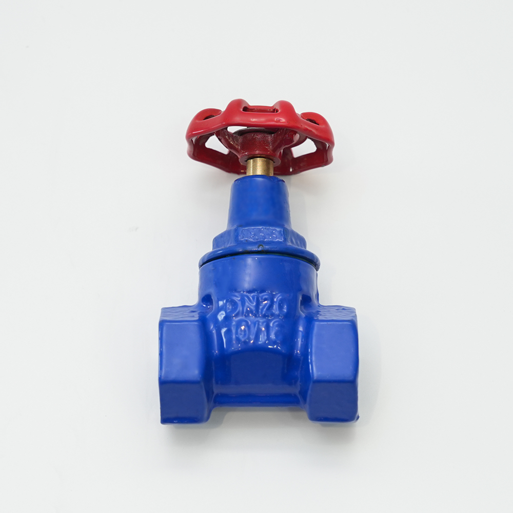
A globe valve is a linear-motion control device that regulates flow by changing the cross-sectional area of the fluid path. Inside the spherical body (which gives the valve its name), a tapered plug or flat disc attached to a rising stem travels toward or away from a circular seat. When the handwheel or actuator turns, the stem lifts the disc, opening an annular orifice that allows fluid to pass. The linear movement provides a proportional relationship between stem travel and flow area, which is why globe valves excel at precise throttling.
Key components include the body, bonnet, disc (or plug), seat ring, stem, and packing. The flow path inside a traditional Z-pattern globe valve is deliberately tortuous: fluid enters below the seat, rises through the orifice, and turns twice before exiting. This S-shaped pathway creates a measurable pressure drop—often a disadvantage in energy-conscious systems—but it is also what gives the globe valve its characteristic controllability. The disc remains aligned with the seat regardless of upstream pressure fluctuations, preventing the chatter that plagues sluice gates and butterfly valves in partially open positions.
Standard port sizes range from 1/2 inch (DN15) to 12 inches (DN300) and larger, with pressure classes from 150 to 2500. While globe valves can be used for isolation, their true design purpose is modulating service. A soft-seated globe valve can achieve bubble-tight shutoff down to Class VI per API 598, but the cost and size penalty compared to a dedicated block valve usually makes them a secondary choice for simple on/off duty.
Types of Globe Valves: Z-Pattern, Y-Pattern, and Angle-Pattern
Three body configurations dominate industrial applications, each trading off flow resistance, serviceability, and installation flexibility.
| Feature | Z-Pattern (Straight) | Y-Pattern | Angle-Pattern |
|---|---|---|---|
| Flow path | S-shaped, changes direction twice | Oblique, straighter flow | 90-degree turn, replaces elbow |
| Pressure drop | Highest | Lower (~30% less than Z) | Moderate |
| Seat accessibility | Difficult (valve in-line) | Easier (bonnet comes off) | Good |
| Typical use | General low-pressure throttling | High-pressure steam, high-temperature oil | Slurry, coking, or systems with solids |
The Z-pattern body is the most common and least expensive to manufacture. Its double change in direction generates a high friction loss, which can be a concern in pumped systems but often acts as a passive damping mechanism that stabilizes downstream flow. Y-pattern valves tilt the stem and disc at approximately 45 degrees relative to the pipeline axis, creating a nearly straight-through passage when fully open. This design reduces turbulence and allows for higher flow capacity at smaller valve sizes, so Y-pattern units are preferred for high-pressure steam and feedwater applications above Class 600.
Angle-pattern globe valves turn the flow 90 degrees, combining the function of a globe valve and an elbow. This configuration is especially useful in refinery coker units, urea synthesis, and other processes where solids buildup would rapidly erode a horizontal seat. The drop-down flow path prevents media from accumulating on the disc and seat, which extends service life and simplifies purging.
Globe Valve vs. Gate Valve vs. Ball Valve for Flow Control
Operators occasionally ask why they cannot simply crack open a gate valve or a standard port ball valve to regulate flow. The answer is tied to fundamental design differences that affect longevity, control precision, and safety.
| Parameter | Globe Valve | Gate Valve | Ball Valve |
|---|---|---|---|
| Intended service | Modulating / throttling | On / off isolation | On / off, limited throttling |
| Flow characteristic | Linear or equal percentage | Quick opening (non-modulating) | Modified percentage |
| Turndown ratio | 30:1 to 50:1 | Not applicable | 20:1 (for characterized ball) |
| Leakage class (API 598) | Class IV (metal seat) to Class VI (soft seat) | Typically Class IV or V | Class VI (soft seat standard) |
| Maintenance cost | Moderate (seat/plug replacement) | Lower (but seat damage if throttled) | Lower, but stem seals can leak |
A ductile iron gate valve uses a wedge or parallel disc that seals by seating against inclined faces. When partially opened, the gate becomes a vibrating obstruction bathed in high-velocity fluid, which quickly grooves the seating surfaces and leads to a leak path that cannot be sealed without replacement. Ball valves, even with characterized V-notches, inherently behave as quick-opening devices that produce poor rangeability—typically around 20:1 for a generic V-port ball—and struggle to maintain linearity below 15% open. Globe valves offer turndown ratios of 30:1 or better with engineered equal-percentage trim, making them the default choice for any loop requiring stable PID control.
Key Selection Parameters: CV Value, Flow Characteristic, and Pressure Drop
Sizing a globe valve begins with the flow coefficient, Cv—the number of US gallons per minute of 60F water that will pass through the valve at 1 psi pressure drop. This single parameter ties together flow rate, pressure drop, and valve opening into an engineering metric that process control specialists use to match the valve to the piping system.
| Valve Opening (%) | Cv (DN25 / 1") | Cv (DN50 / 2") |
|---|---|---|
| 20% | 2 | 8 |
| 50% | 8 | 30 |
| 80% | 14 | 60 |
| 100% | 16 | 75 |
A proper Cv calculation—often done with the ISA 75.01.01 equation—incorporates the required maximum flow, available pressure drop, and geometry factors. Selecting a valve that operates between 20% and 80% open at normal flow avoids the deadband at both extremes where turbulence and cavitation risk spike.
Equally important is the flow characteristic. Linear trim gives a flow increase directly proportional to stem travel, while equal-percentage trim yields equal increments of flow for equal increments of stem travel at constant pressure drop. The latter is essential in loops where the pressure drop across the valve changes significantly with flow—for example, when a heat exchanger in series causes a variable backpressure. In such systems, an equal-percentage globe valve compensates for the nonlinear loop gain and maintains a stable controller output range. Oversimplifying this choice can render a well-specified valve almost uncontrollable.
Material Selection Guide for Globe Valves
Choosing the right body and trim material determines whether a globe valve lasts twenty years or fails in six months. The decision tree starts with the process fluid chemistry and temperature.
| Medium | Temperature Range | Body Material | Trim Material | Notes |
|---|---|---|---|---|
| Steam | -20 C to 400 C | Cast steel (WCB) | Stainless steel 316L | Requires high-temperature packing |
| Water (municipal) | 0 C to 80 C | Ductile iron | Bronze or stainless | Cost-effective, good for low pressure |
| Acids / alkalis | -20 C to 200 C | Stainless steel 316L | Stainless or PTFE | Excellent corrosion resistance |
| Oil (hydrocarbon) | -30 C to 350 C | Cast steel or stainless | 13Cr or stainless | Avoid soft seals if aromatics present |
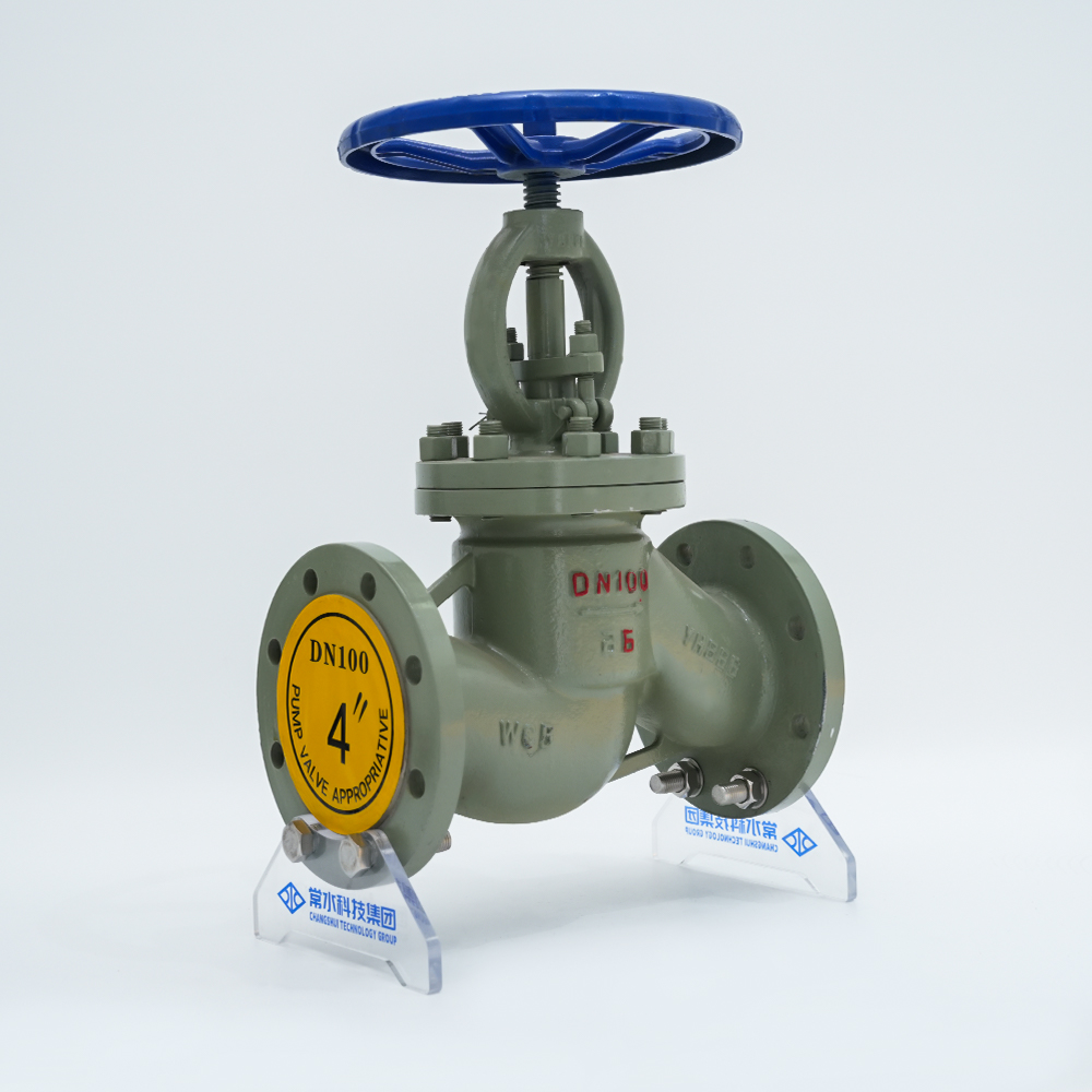
Cast steel WCB is the standard material for saturated and superheated steam up to 400 C, and it delivers reliable performance in feedwater and condensate return lines. For high-temperature steam applications, the cast steel globe valve J41H-16C provides reliable performance up to 400 C with 13Cr stainless trim. When the medium shifts to aggressive chemicals, 316L stainless steel resists pitting and intergranular corrosion far better than carbon steel, and the seat can be further enhanced with Stellite hardfacing or PTFE inserts to handle acids at moderate temperatures.
In low-pressure water distribution networks, ductile iron bodies with bronze internals offer a 40–50% cost saving over cast steel without sacrificing sealing integrity below PN16. The catch is that ductile iron has a lower temperature ceiling (typically 100 C) and loses impact resistance in sub-zero service. Always verify the material compatibility chart for the specific chemical cocktail at the design temperature—minor constituents such as chlorides or hydrogen sulfide can invalidate a seemingly conservative selection.
Installation and Maintenance Best Practices
A correctly specified globe valve can still fail prematurely if installation rules are ignored. The most common mistake is reversing the flow direction. Globe valves are directional by design—flow must enter under the seat so that when the valve closes, the disc assists the seat against pressure rather than fighting it. A backward installation leads to hammering, reduced Cv, and rapid seat erosion.
- Verify the flow arrow on the valve body. In Y-pattern valves, the orientation often reverses for high-temperature service to keep the stem cooler, so always consult the manufacturer's data sheet.
- Provide straight pipe lengths: at least 5 diameters upstream and 2 diameters downstream. This preserves the calibrated flow characteristic and prevents jet-induced vibration.
- For steam lines, account for thermal expansion. Install expansion loops or sliding supports to avoid stem binding, and allow the valve to heat-soak gradually during startup.
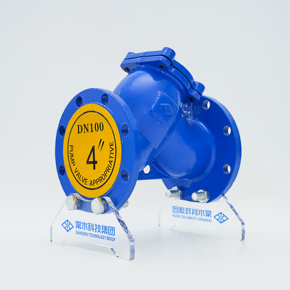
- Protect the seat. Installing a Y-type strainer upstream removes weld slag, mill scale, and pipe tape that would otherwise score the disc and seat faces and destroy the sealing surface within days.
Routine inspection should focus on the disc and seat contact surface. A simple bench check of the leakage rate against the original Class IV or VI specification reveals whether the seat needs lapping or replacement. Stem packing requires re-torque every 500 cycles or whenever a gland leak appears; tightening too aggressively, however, can increase stem friction and reduce controller accuracy in automated systems.
Common Applications of Globe Valves in Industrial Systems
Globe valves appear wherever a process demands consistent, repeatable flow modulation—from the boiler room of a district heating plant to the sampling panel of a refinery crude unit.
| Industry | Application | Recommended Type |
|---|---|---|
| Power generation | Feedwater control, steam vents | Y-pattern, cast steel, Class 300+ |
| Chemical processing | Corrosive media throttling | Angle pattern, stainless steel 316L |
| HVAC / district heating | Chilled water, hot water balancing | Z-pattern, ductile iron, PN16 |
| Oil & gas | Crude oil sampling, drain valves | Y-pattern, cast steel, Class 600 |
In power plants, the boiler feedwater recirculation line relies on a high-differential globe valve to prevent pump cavitation at low flow. The same valve type serves as the final element in a steam attemperator loop, injecting cooling water with millisecond-level modulation. Chemical plants favor angle-pattern bodies for reactor drain services because the straight-through bottom port eliminates pockets where polymer or salt could accumulate and block the valve. Stainless steel globe valves with graphoil packing handle nitric acid, caustic soda, and solvent mixtures at process temperatures that would embrittle carbon steel in hours.
Even in less dramatic settings—a campus chilled water loop, a hotel heating manifold—globe valves fitted with electric actuators hold return water temperature within a degree by precisely mixing hot and cold streams. The same valve assembly, swapped to a different trim material, can run for two decades in municipal water service with only an annual packing check.
How to Choose the Right Globe Valve for Your Flow Control Needs
Distilling the selection process into systematic steps removes guesswork and avoids the common pitfalls that create maintenance nightmares.
- Define the process conditions: fluid type, maximum inlet pressure, design temperature, and required turndown ratio. Write these down as the non-negotiable performance envelope.
- Calculate the required Cv at maximum and minimum operating flow using the ISA standard equations. Target a valve stroke between 20% and 80% in normal control range.
- Select the flow characteristic. Use equal percentage for loops where the system delta-P varies; use linear only when the process gain is constant throughout the flow range.
- Choose body and trim materials from a validated chemical compatibility chart. Then pick the pressure class and connection standard (flanged, butt-weld, or threaded) to match your piping specification.
- Verify the actuator sizing—pneumatic, electric, or electro-hydraulic—based on the required stem force at maximum differential pressure, then add the fail-safe condition (fail-open, fail-closed, or lock-in-place).
When the datasheet matches the operating reality, a globe valve becomes the quiet workhorse that process engineers trust. Its simple mechanism yields predictable control, its replaceable trim makes maintenance straightforward, and its range of material options covers everything from chilled brine to superheated steam.